Magnet valve
- Summary
- Abstract
- Description
- Claims
- Application Information
AI Technical Summary
Benefits of technology
Problems solved by technology
Method used
Image
Examples
Embodiment Construction
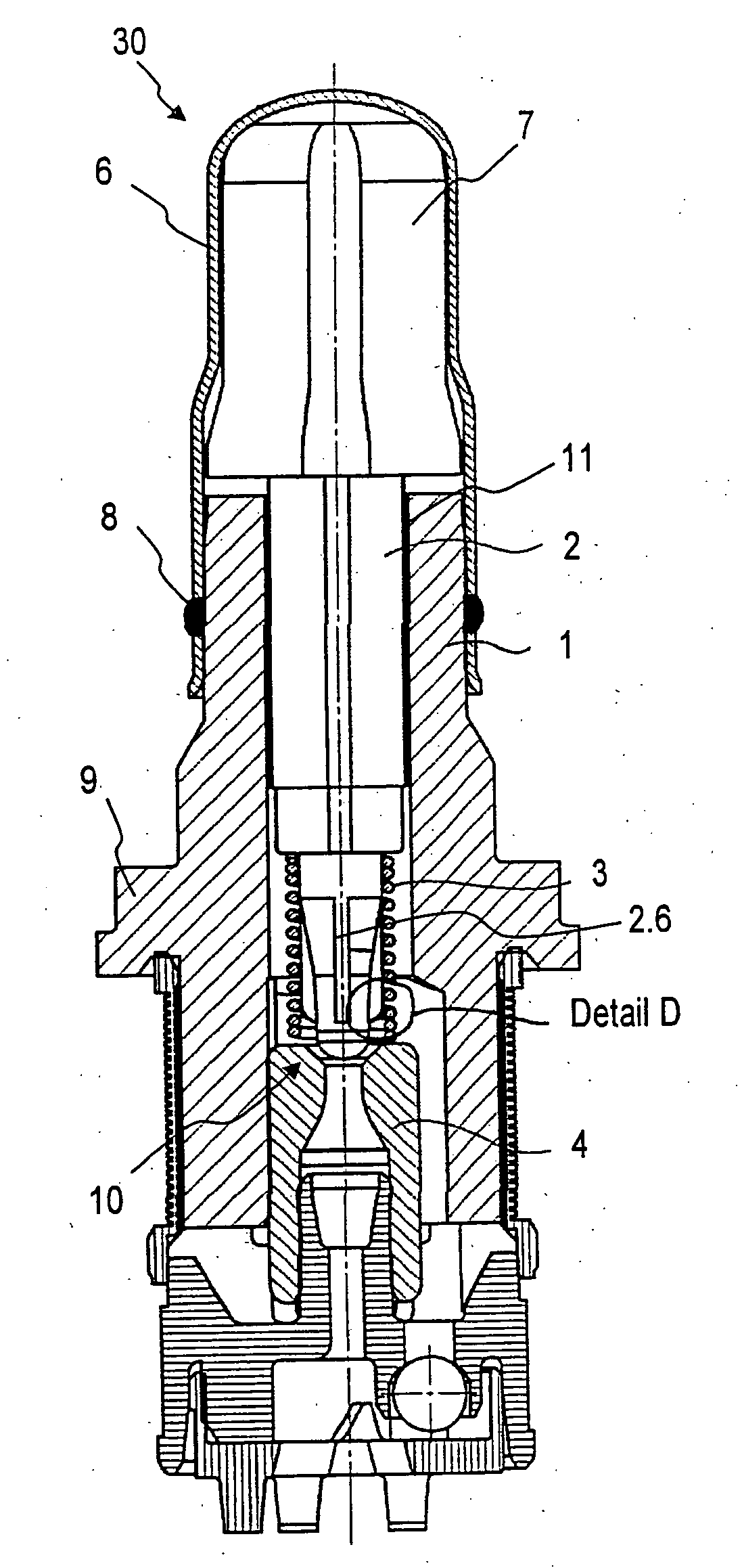
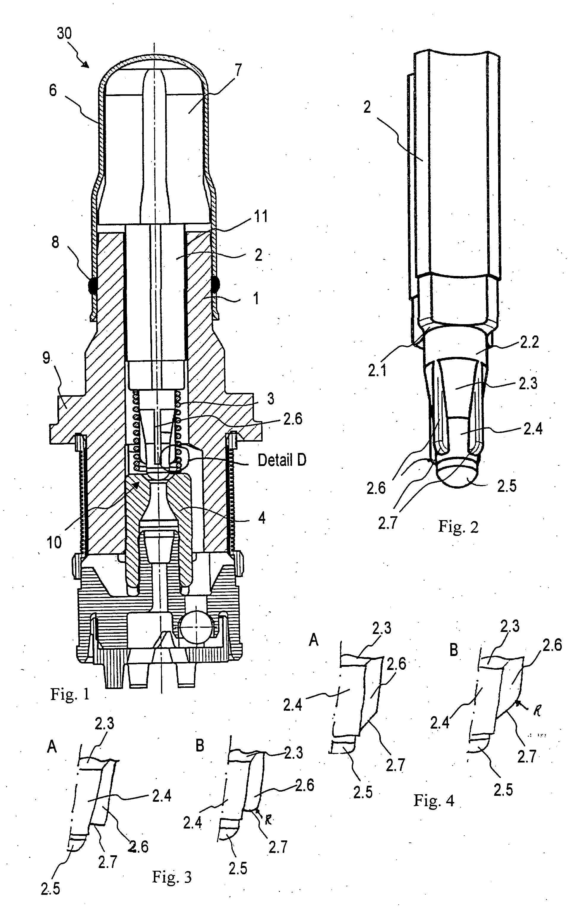
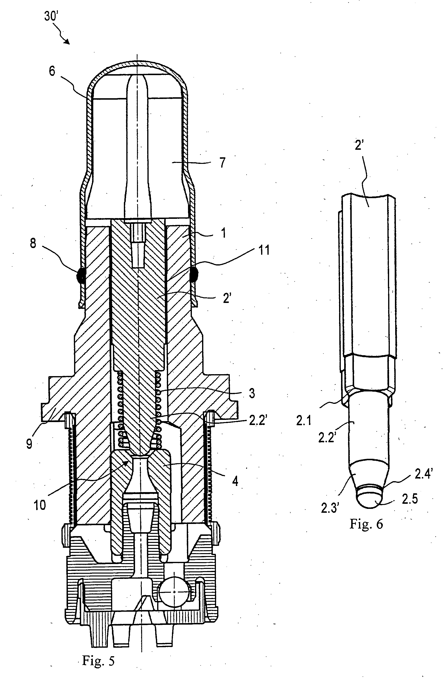
[0020]As can be seen from FIG. 1, a magnet valve 30 of the invention, besides a magnet assembly, not shown, has a valve cartridge, which analogously to the conventional magnet valve 40 of FIG. 7 includes a capsule 6, a valve insert 1, a tappet 2, a restoring spring 3, and an armature 7. In the production of the magnet valve 30, the capsule 6 and the valve insert 1 of the valve cartridge are joined together by pressing, and by means of a sealing weld 8, the valve cartridge is hydraulically sealed off from the atmosphere. In addition, the valve insert 1 absorbs the pressure forces that occur in the hydraulic system and conducts them onward via a calked flange 9 to a calked region, not shown, on a fluid block. The valve insert 1 also receives the so-called valve body 4, which includes a valve seat 10 into which the tappet 2 plunges in sealing fashion in order to accomplish the sealing function of the magnet valve 30. As also seen from FIG. 1, the tappet 2 is guided via a tappet guide 1...
PUM
 Abstract
Description
Claims
Application Information
 - R&D
- Intellectual Property
- Life Sciences
- Materials
- Tech Scout
- Unparalleled Data Quality
- Higher Quality Content
- 60% Fewer Hallucinations
Browse by: Latest US Patents, China's latest patents, Technical Efficacy Thesaurus, Application Domain, Technology Topic, Popular Technical Reports.
© 2025 PatSnap. All rights reserved.Legal|Privacy policy|Modern Slavery Act Transparency Statement|Sitemap|About US| Contact US: help@patsnap.com


