
Portable safety barrier

a safety barrier and portability technology, applied in protective construction, roads, construction, etc., can solve problems such as damage to persons or properties, and achieve the effect of convenient manual rewinding and easy rewinding of nets

Inactive Publication Date: 2007-08-02
ROBINSON JEFFERY A
View PDF24 Cites 37 Cited by
  • Summary
  • Abstract
  • Description
  • Claims
  • Application Information

AI Technical Summary

Benefits of technology

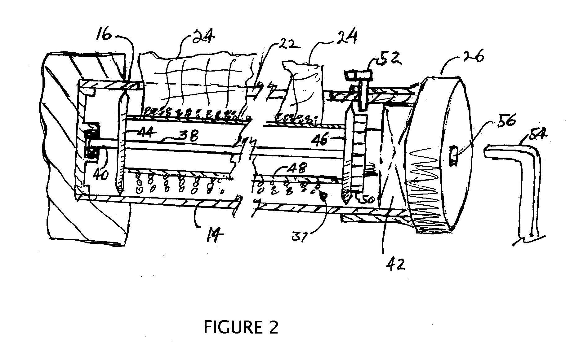
[0015] The frame includes a manually operated rewind system both to apply tension to the net so it establishes a taut barrier when deployed and to rewind the net after use. The rewind system includes a gear train that provides a mechanical advantage to facilitate the manual rewinding of the net onto the core. The system also includes a one-way stop that is selectively engaged after the net is deployed to prevent the further extension of the net from the core. After the stop is engaged, operation of the rewind system causes the net to tighten between the remote post and the frame. The stop is released to allow easier rewinding of the net back to a stored position on the core.

Problems solved by technology

For example, children often are apt to pursue a ball, toy or pet and not recognize that the pursuit is leading to an unsafe area.
Otherwise, if the net and post are left free to move, the bias can rewind the net with such force that damage to person or property can result.

Method used


Image

  • Portable safety barrier
  • Portable safety barrier
  • Portable safety barrier

Examples


Embodiment Construction

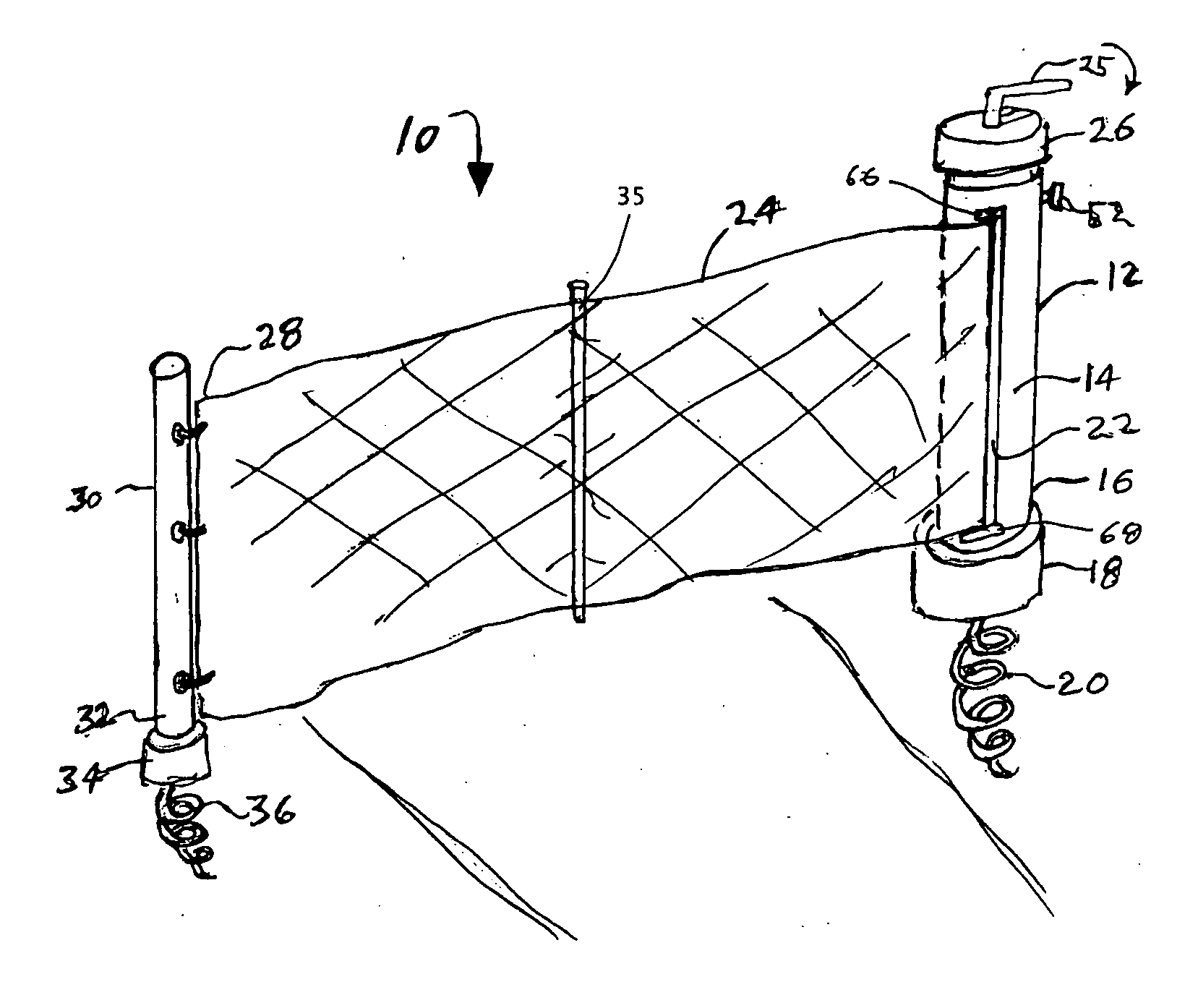
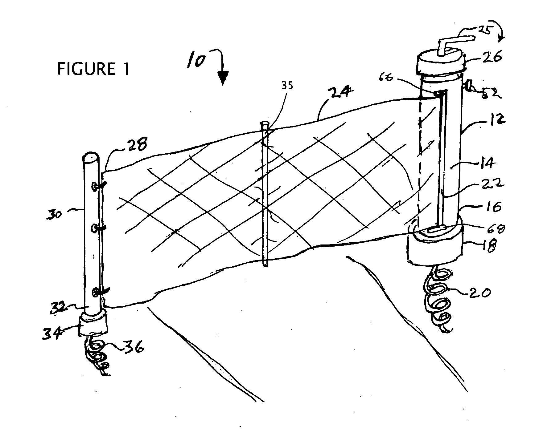
[0031] Referring to the drawings, FIG. 1 shows the portable safety barrier apparatus of the present invention generally indicated at 10. The apparatus includes a frame or housing 12 formed by a generally tubular outer shell 14. The shell lower end 16 has or is releaseably received in a supply side holder 18. An auger 20 extends from a lower surface of the supply side holder 18 to facilitate the anchoring of the main housing to ground. The housing 12 represents the main support post of the barrier.

[0032] As seen in FIGS. 3 and 5, the supply side holder 18 can be screwed, or augered into the ground via the auger 20. The supply side holder 18 includes a cup or sleeve shape recess to receive the frame 10. The supply side holder 18 can include a pair of collinear apertures 19 sized to receive a lever or rod 62 for increasing leverage on the auger 20 to assist in engaging the ground.

[0033] The outer shell 14 has an elongated slot 22. Extending through the slot is a barrier net 24. The n...


PUM


Abstract

A portable safety barrier that can be set up across a drive way or other path to provide a visible and physical indication of a safe zone boundary particularly for children. Netting attached to a core or reel disposed in a housing forms the barrier. The netting is free to deploy from the housing for attachment to a remote post; both the housing and post including an auger for anchoring the housing and post to ground. The housing has a rewind system to reel in the netting which includes a gear train for mechanical advantage. The rewind system operates manually and with out a bias assist. A selectively operated stop cooperates with the rewind system to tighten the netting after deployment and keeps the netting taut.

Description

CROSS-REFERENCE TO RELATED APPLICATIONS [0001] Not applicable. STATEMENT REGARDING FEDERALLY SPONSORED RESEARCH OR DEVELOPMENT [0002] Not applicable. REFERENCE TO A “SEQUENCE LISTING”[0003] Not applicable. BACKGROUND OF THE INVENTION [0004] 1. Field of the Invention [0005] The present invention relates generally to a barrier as may be set up as a temporary boundary to discourage movement into or out of a restricted or dangerous area. More particularly, the invention relates to a portable apparatus used to set a barrier that works to identify the boundary of a safe zone, particularly for children, and to discourage passage into or out of the zone. [0006] 2. Description of Related Art [0007] Children at play are often oblivious to dangers inherent in spontaneous activity. For example, children often are apt to pursue a ball, toy or pet and not recognize that the pursuit is leading to an unsafe area. For this reason, various types of apparatus are available to set temporary barriers to...

Claims


Application Information

Patent Timeline
IPC IPC(8): E01F7/02
CPCE01F13/028
Inventor ROBINSON, JEFFERY A.
Owner ROBINSON JEFFERY A
Learn More