Exhaust pipe joint with insert

a technology of exhaust pipe joints and inserts, which is applied in the direction of hose connections, machines/engines, mechanical equipment, etc., can solve the problems of inflicting significant damage, corrosion can dissipate dynamic stresses associated, and inflict significant damage,

Inactive Publication Date: 2007-08-02
TRU FLEX
View PDF18 Cites 21 Cited by
  • Summary
  • Abstract
  • Description
  • Claims
  • Application Information

AI Technical Summary

Benefits of technology

[0012] In the practice of the present invention, a metal conduit assembly is provided which includes a corrugated conduit section, at least one mating pipe, a clamp, and a seal element. The clamp incorporates a constriction means to releasably join the corrugated conduit, seal and mating pipe in a clamped relationship. The seal may be a split band having adjacent free ends or a band having slots arranged in a stair-step pattern. The ends of a split band seal are drawn together when the seal is constricted by the clamping action. The corrugated conduit may include a smooth neck portion with outwardly extending nodules or clamp stops to limit the axial movement of the clamp along the corrugated conduit. This prevents the clamp from engaging and possibly damaging the corrugations.
[0014] The seal can have one or more internal dimples to limit insertion of the exhaust pipe to a point where it cannot damage the corrugations. The corrugated or strip-wound pipe can be provided with a flared sleeve having an end extension which extends into the pipe to transfer vibrational forces away from the weld joint connecting the sleeve to the corrugated or strip-wound pipe.

Problems solved by technology

Moreover, corrugations can dissipate dynamic stresses associated with the vibration of the components to which the flexible hose section is attached.
However, torsional forces caused by the differential rotation of the exhaust system components connected by a flexible metal hose section can inflict significant damage, particularly when the flexible hose section ends are fixedly secured and the flexible section design is rigid with respect to rotational forces.
Such dynamic torsional forces can lead to premature metal fatigue, cracking and failure of exhaust system components, including previous designs of flexible metal hose.
While this system has worked well, it is not wholly without problems.
However, the corrugated pipe is crushed and crumpled in the process because of its initially loose fit, thus leading to leakage at this joint.
This is a serious problem and even more serious in the case of a system of the type shown in the pending Thomas application because crushing of the corrugated pipe can result in deformation extending to the corrugations.
If that happens, the corrugations can be damaged to the point where relative rotation of the corrugated pipes is impeded or prevented altogether, thus resulting in failure of the system.
Another problem is that the clamp can slide on the pipe and possibly bang into and damage the corrugations as the clamp is being applied.
This damage can lead to the same unacceptable result.

Method used


Image

  • Exhaust pipe joint with insert
  • Exhaust pipe joint with insert
  • Exhaust pipe joint with insert

Examples


Embodiment Construction

[0028] Detailed embodiments of the present invention are described herein with reference to the Figures. The specific structural and functional details disclosed herein are intended to be exemplary and should not be interpreted as limiting the invention.

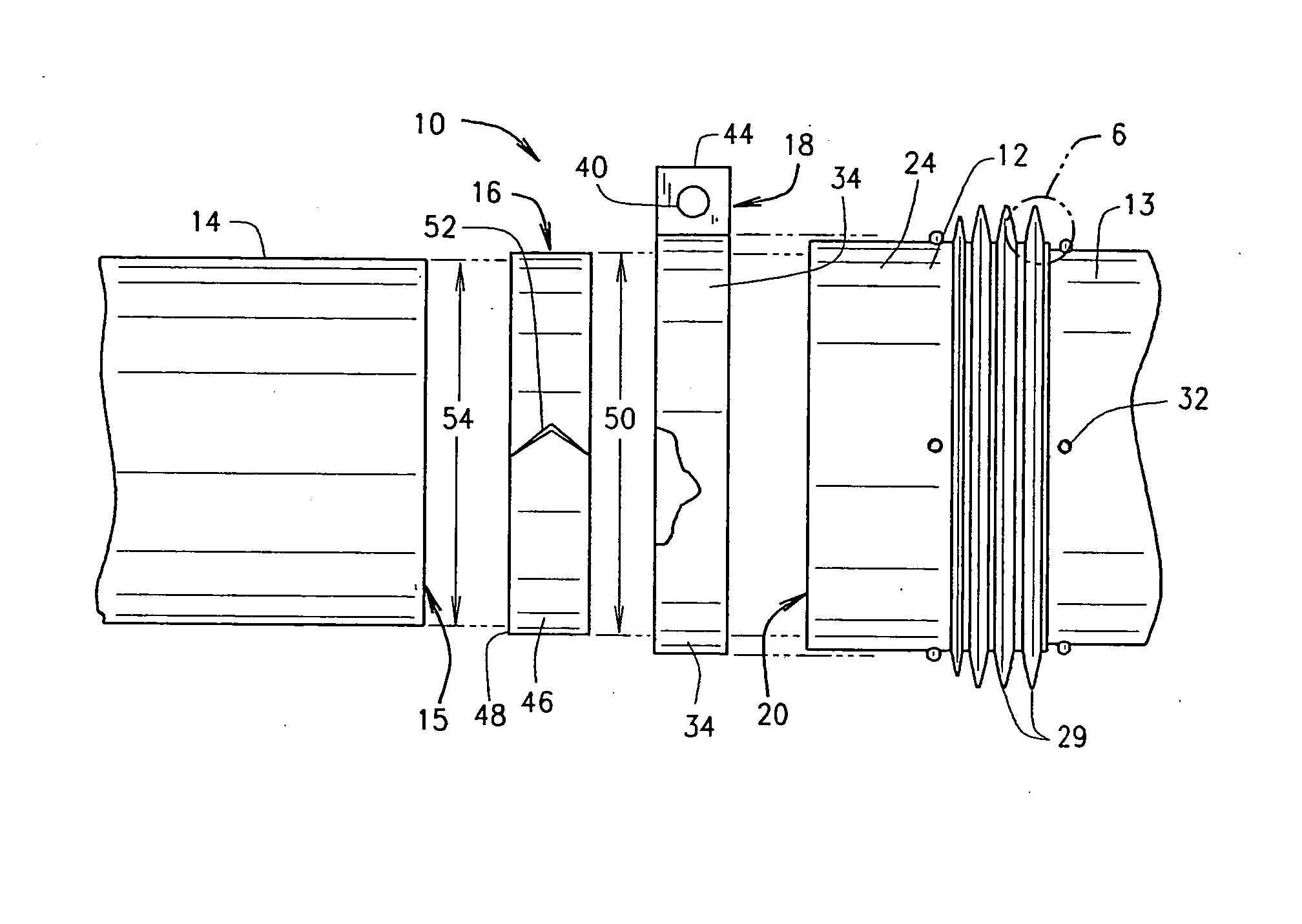
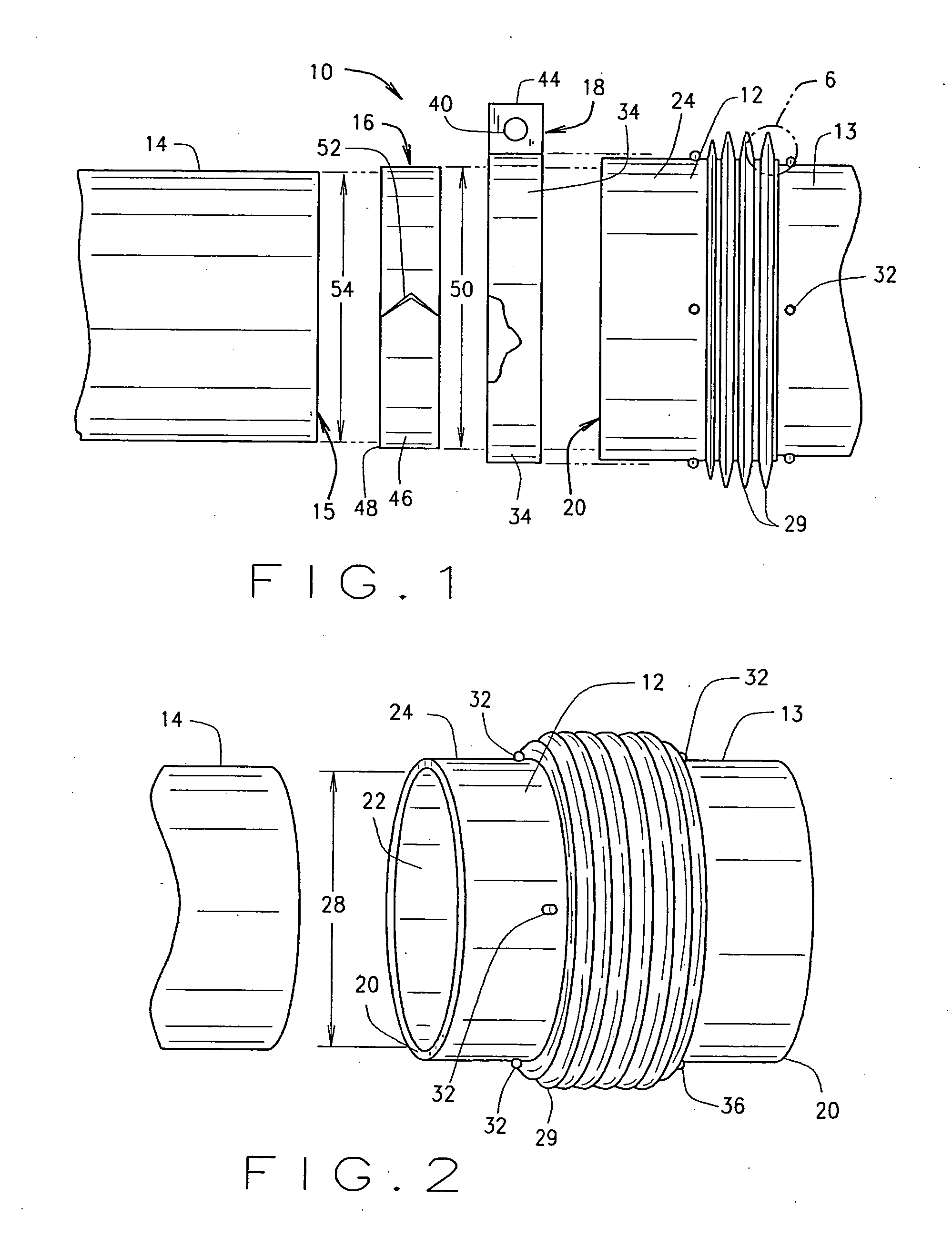
[0029] Referring to the drawings in detail, and initially to FIG. 1, the reference number 10 generally designates a pipe assembly constructed in accordance with one embodiment of coupling the present invention. The assembly 10 comprises a pair of corrugated conduits 12 and 13, a pipe 14, seal element 16, and a clamp 18, each having a generally circular transverse cross-sectional configuration.

[0030] The conduit 12 has a free end 20 and a series of corrugations 29 spaced from end 20. The conduit 12 further comprises a bore 22 to accommodate flow of fluid or gases, e.g., vehicular exhaust gases. Located adjacent to the end 20 is a smooth-walled neck portion 24 of conduit 12.

[0031] The conduit 12 has a generally circular transverse c...


PUM

PropertyMeasurementUnit
V angleaaaaaaaaaa
angleaaaaaaaaaa
movementaaaaaaaaaa

Abstract

A connection assembly for pipes is provided. The assembly includes a pipe, a corrugated conduit, a circumferentially expandable and contractable seal positioned between portions of the conduit and the pipe and a clamp encircling the conduit, seal and pipe. The seal is circumferentially contractible to secure the conduit and the pipe together with the seal serving to effect a gas-tight seal while filling the annular gap between the conduit and pipe. Additional embodiments provide flared sleeves on the corrugated conduit and stops for limiting movement of the components.

Description

BACKGROUND OF THE INVENTION [0001] The present invention generally relates to the field of pipe assemblies such as those used in vehicular exhaust systems and more particularly to an assembly having corrugated conduits that are clamped onto rigid piping and utilize a metal seal element to provide a fluid-tight connection therebetween. The present invention further provides a system that minimizes possible damage to the corrugations of the conduit. [0002] Conduit and piping systems for conveying fluids and bulk materials are used in a wide variety of applications. Various components for such systems have been devised to accommodate different fluids and materials and to operate in particular environments. For example, some of the components of such systems are fabricated from flexible metal hose, which offers the advantages of durability, flexibility, relatively low cost and adaptability to various sizes, configurations and materials. [0003] Flexible metal hose has been used for many ...

Claims


Application Information

Patent Timeline
Patent Type & Authority Applications(United States)
IPC IPC(8): F16L51/02F01N13/08F01N13/18
CPCF01N13/1816F01N13/1827F16L33/04F01N2450/18F16L21/065F01N13/1844Y10S285/917Y10S285/903
Inventor SWANK, SCOTT R.
Owner TRU FLEX
Why Eureka
Try Eureka