Organic el element

a technology of organic elements and elements, applied in the direction of discharge tube luminescnet screens, other domestic articles, organic semiconductor devices, etc., can solve the problems of dust attachment, process damage, deterioration of emission quality,

Active Publication Date: 2007-08-02
LG DISPLAY CO LTD
View PDF2 Cites 6 Cited by
  • Summary
  • Abstract
  • Description
  • Claims
  • Application Information

AI Technical Summary

Benefits of technology

[0011] According to an aspect of the present invention, there is provided an organic EL element comprising: a first electrode; a protection layer that is formed on the first electrode and has a first opening portion through which the first electrode is exposed; an insulation layer formed on the protection layer and having a second opening portion in a region corresponding to the first opening portion of the protection layer; an organic layer that is formed over the insulation layer and the first electrode exposed through the first opening portion, and includes an emission layer; and a second electrode formed on the organic layer. In this case, a film thickness of the protection layer is less than that of the organic layer.
[0012] According to another aspect of the present invention, there is provided an organic EL element comprising: a first electrode; a protection layer formed on the first electrode and having a concave portion; an insulation layer formed on the protection layer and having an opening portion through which the protection layer is exposed; an organic layer that is formed over the insulation layer and the protection layer through which the opening portion of the insulation layer, and includes an emission layer; and a second electrode formed on the organic layer. In this case, a depth of the concave portion is less than a film thickness of the organic layer.

Problems solved by technology

However, while the first electrode is subjected to the above processes, process damage may occur, or dust may be attached onto the first electrode.
This affects to a characteristic of the organic EL element, which leads to deterioration in emission quality.

Method used


Image

  • Organic el element
  • Organic el element
  • Organic el element

Examples


first embodiment

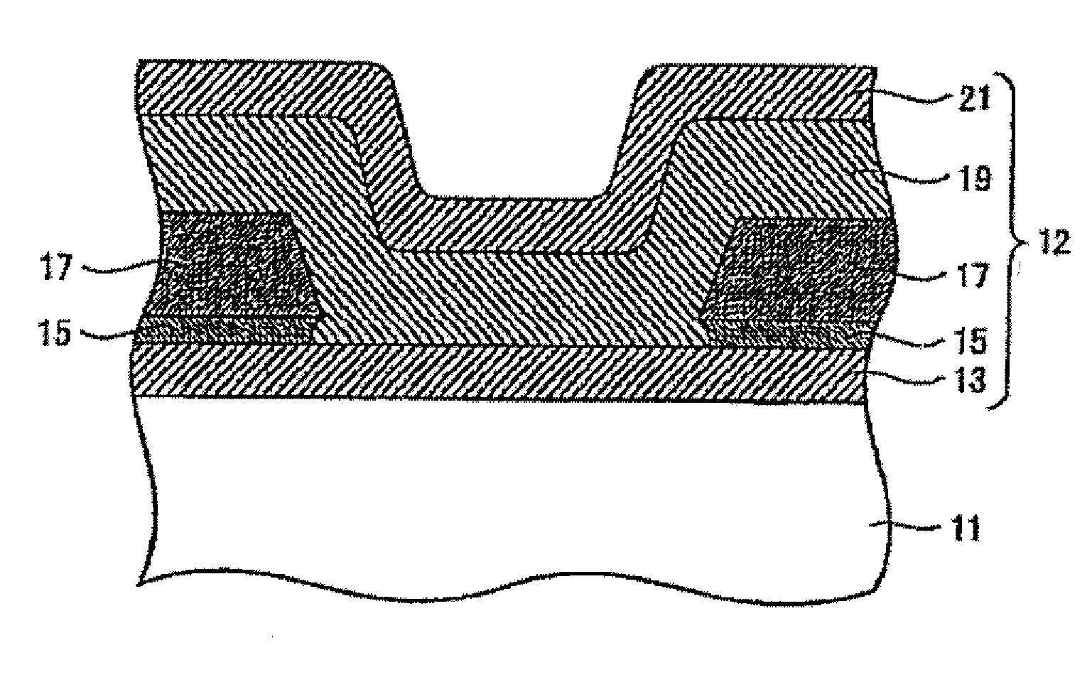
[0020]FIG. 1 is a cross-sectional view showing a schematic structure of an organic EL element according to a first embodiment of the present invention. As illustrated in FIG. 1, the organic EL element includes a substrate portion 11 and an organic electroluminescence element portion 12 on the substrate portion 11. The substrate portion 11 includes a substrate such as a glass substrate, a driving element such as a TFT used to drive the organic electroluminescence element portion 12, a conductive pattern, and a flattening layer which covers the driving element and the conductive pattern. The organic EL element employs a top emission type structure in which light is obtained from a top surface side of the organic electroluminescence element portion 12.

[0021] As illustrated in FIG. 1, the organic electroluminescence element portion 12 includes a lower electrode (anode electrode) 13 that is a first electrode formed on the substrate portion 11, a protection layer 15 that is formed on the...

second embodiment

[0057]FIG. 10 is a cross-sectional view showing a structure of the organic EL element according to a second embodiment of the present invention. The following description will focus on a different structure from the organic EL element according to the first embodiment of the present invention, and the rest of common structures will be basically omitted.

[0058] Unlike the first embodiment, in the second embodiment, the protection-material layer 15a existing within the opening portion of the interlayer-insulation layer 17 is not entirely removed, instead thereof, the protection-material layer 15a existing within the opening portion of the interlayer-insulation layer 17 remains so as to form a concave portion 15b in the protection layer 15. As a result, the film thickness of the protection layer 15 within an inner area of the opening portion of the interlayer-insulation layer 17 is less than that of the protection layer 15 outside the opening portion of the interlayer-insulation layer ...


PUM


Abstract

Provided is an organic EL element including: a first electrode 13; a protection layer 15 that is formed on the first electrode 13 and has an opening portion through which the first electrode 13 is exposed; an insulation layer 17 that is formed on the protection layer 15; an organic layer 19 that is formed over the insulation layer 17 and the first electrode 13 exposed through the opening portion, and includes an emission layer; and a second electrode 21 formed on the organic layer 19, wherein a film thickness of the protection layer 15 is less than that of the organic layer 19.

Description

CROSS-REFERENCE TO RELATED APPLICATIONS [0001] The present application claims priority under 35 U.S.C. §119 to Japanese Patent Application No. 2005-220976, filed Jul. 29, 2005 and Japanese Patent Application No. 2006-148927, filed May 29, 2006. The contents of this application are incorporated herein by reference in their entirety. BACKGROUND OF THE INVENTION [0002] 1. Field of the Invention [0003] The present invention relates to an organic EL element. [0004] 2. Description of the Related Art [0005] In an organic electroluminescence (EL) element, an electric field is applied to an organic fluorescent compound so as to be excited to emit light. Characteristics of the organic EL element include self-illumination, a wide viewing angle, a high response speed, a low driving voltage, and full color. The organic EL element has currently been put to practical use, and may apply to a flat color display device such as a compact display panel, an out-door screen, or a screen for a personal co...

Claims


Application Information

Patent Timeline
Patent Type & Authority Applications(United States)
IPC IPC(8): H01L51/52
CPCH01L2251/5315H01L27/3246Y10S428/917H10K59/122H10K2102/3026H05B33/22
Inventor KANOH, KEIGOMOROOKA, MITSUOHASUMI, TAROFUKUOKA, HIROMIWATANABE, MASAYA
Owner LG DISPLAY CO LTD
Why Eureka
Try Eureka