Secondary battery

a battery and secondary technology, applied in the field of secondary batteries, can solve the problems of reducing battery performance, difficult to efficiently use conventional drawing process, and difficulty in firmly joining seams with no gaps by laser welding, so as to reduce the strength of the battery case, reduce the battery performance, and reduce the strength of the lid member

Pending Publication Date: 2022-08-04
PRIME PLANET ENERGY & SOLUTIONS INC
View PDF3 Cites 0 Cited by
  • Summary
  • Abstract
  • Description
  • Claims
  • Application Information

AI Technical Summary

Benefits of technology

[0011]In accordance with one effective aspect of the secondary battery herein disclosed, the second member is formed by the extruding process to have a cylindrical shape that is continuously extending with no seams. In this case, the second member is cylindrical and no seams are formed at the ring-shaped opposite ends of the second member. Accordingly, it does not happen that, when a lid member is joined to the open end of the second member, the join strength of the lid member is reduced by the seams, which is different from, for example, the case where a metal plate is deformed to have a ring-shape and is joined so as to use the second member. Thus, the strength of the battery case can be secured further properly.
[0012]In accordance with one effective aspect of the secondary battery herein disclosed, the second member is joined by the ultrasonic join process in a state fitting the second member to the cylindrical portion of the first member. In this case, it is rare that leak, or the like occurring at the join process reduces the battery performance, which is different from the case where the first member and the second member are joined by the laser welding. In addition, the ultrasonic join process is performed in a state pressing the fit portions of the first member and the second member, and thus it is rare that a gap occurs on the join portion, in comparison with the case where the laser welding, or the like is used. Thus, the battery case can be formed efficiently and properly.
[0013]In accordance with one effective aspect of the secondary battery herein disclosed, the power generating element includes an electrolyte, and the cylindrical portion of the first member is fit to the outer circumferential part of the cylindrical second member. In this case, it is easy to make the capacity of the bottomed cylindrical first member be larger, in comparison with the case where the cylindrical portion of the first member is fit to the inside of the second member. Accordingly, arranging the first member at the bottom part of the secondary battery would facilitate properly accumulating the electrolyte at the bottom part of the first member.
[0014]In accordance with one effective aspect of the secondary battery herein disclosed, the power generating element includes a wound electrode body. The wound electrode body is formed by winding a sheet-shaped positive electrode and a sheet-shaped negative electrode through a separator. The wound electrode body includes a pair of R parts in which the wound positive electrode, the wound negative electrode, and the wound separator are bent. One of the pair of R parts of the wound electrode body is arranged at the position of the ring-shaped open end positioned at the opposite side to the bottom part of the first member or arranged at the position closer to the bottom part side than the open end. In this case, the depth of the bottomed cylindrical first member is secured to sufficiently fit the cylindrical portion of the first member to the second member. Therefore, it further facilitates securing the join strength of the first member to the second member.

Problems solved by technology

However, regarding the technique described in the above-described cited document, it is quite difficult to firmly join the seams with no gaps by the laser welding in a state where end parts of plural members are opposed accurately to each other.
However, in the drawing process, portions (non-use portion), which cannot be used as the battery case and thus would be scrapped or the like, among the material of the metal plate would occur often.
Accordingly, it has been difficult for the conventional drawing process to efficiently form the bottomed cylindrical battery case having a sufficient depth capable of accommodating the power generating elements of the secondary battery.
In this case, it is rare that leak, or the like occurring at the join process reduces the battery performance, which is different from the case where the first member and the second member are joined by the laser welding.

Method used


Image

  • Secondary battery
  • Secondary battery
  • Secondary battery

Examples


Embodiment Construction

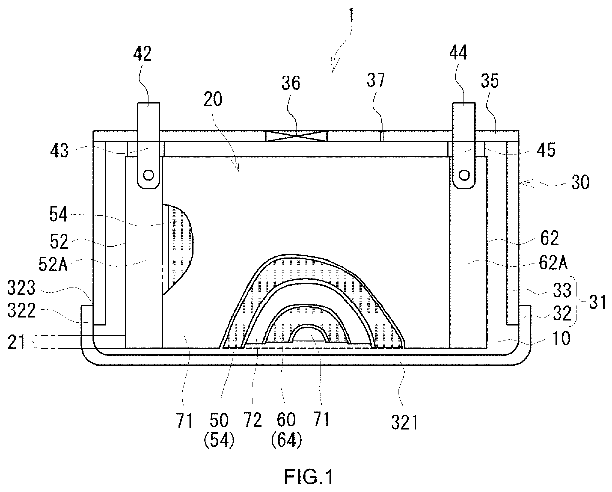
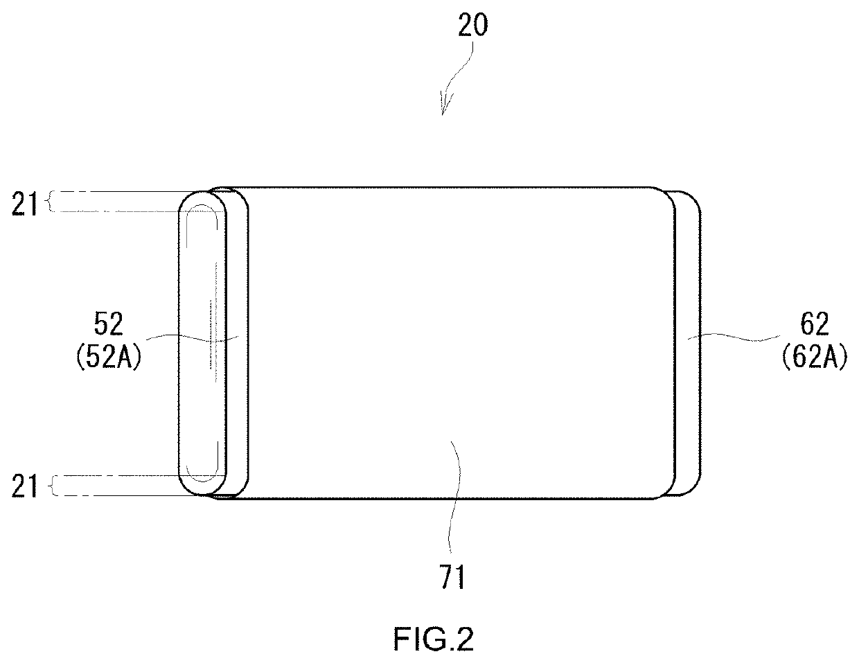
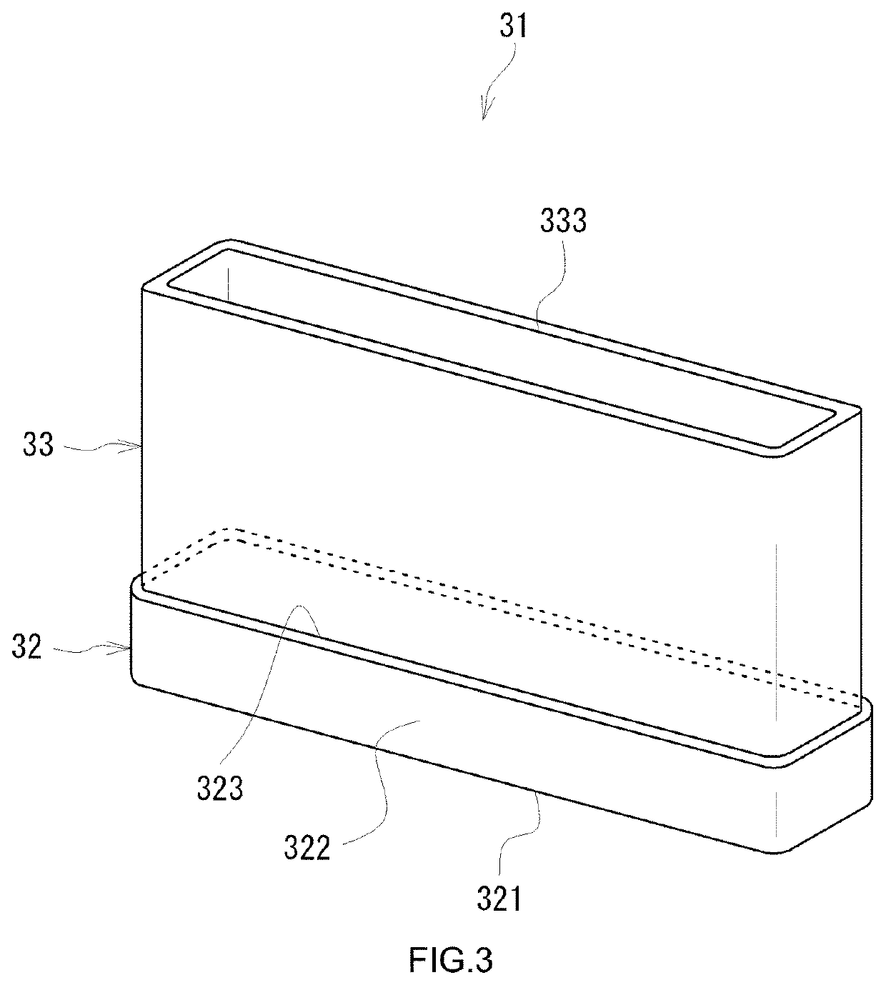
[0018]Below, one of typical embodiments in the present disclosure will be described in details by reference to the accompanying drawings. The matters other than matters particularly mentioned in this specification, and required for practicing the present invention can be grasped as design matters of those skilled in the art based on the related art in the present field. The present teaching can be executed based on the contents disclosed in the present specification, and the technical common sense in the present field. Incidentally, in the following accompanying drawings, the members / parts providing the same effect are given the same numerals and signs. Further, the dimensional relation (such as length, width, or thickness) in each drawing does not reflect the actual dimensional relation.

[0019]In the present specification, “battery” is a term denoting an electric storage device capable of extracting the electric energy in general, and is a concept including a primary battery and a s...


PUM

PropertyMeasurementUnit
poweraaaaaaaaaa
cylindrical shapeaaaaaaaaaa
rigidityaaaaaaaaaa

Abstract

A secondary battery herein disclosed includes a case main body. The case main body accommodates a power generating element in the inside. The case main body includes a first member and a second member. The first member is bottomed cylindrical and formed from one metal plate by a drawing process. The shape of the second member is cylindrical. The second member is joined in a state fitting the second member to a cylindrical portion of the first member.

Description

CROSS-REFERENCE TO RELATED APPLICATIONS[0001]The present application claims the priority based on Japanese Patent Application No. 2021-016289 filed on Feb. 4, 2021, the entire contents of which are incorporated in the present specification by reference.BACKGROUND OF THE INVENTION1. Field of the Invention[0002]The present teaching relates to a secondary battery including a power generating element accommodated inside a battery case having rigidity.2. Description of the Related Art[0003]A secondary battery has been widely used as a portable power supply for a personal computer, a portable terminal, or the like, or used as a power supply for driving automobiles, such as EV (electric vehicle), HEV (hybrid electric vehicle), and PHEV (plug-in hybrid electric vehicle). A laminate type battery case having flexibility, a rectangular cylindrical or circular cylindrical battery case having rigidity or the like has been known as the battery case of the secondary battery. The battery case havin...

Claims


Application Information

Patent Timeline
Patent Type & Authority Applications(United States)
IPC IPC(8): H01M50/107H01M10/0587H01M50/119
CPCH01M50/107H01M50/119H01M10/0587H01M50/166H01M10/0431Y02P70/50H01M10/0525H01M50/103
Inventor SAKURAI, TAKAHIRO
Owner PRIME PLANET ENERGY & SOLUTIONS INC
Why Eureka
Try Eureka