Lens barrel assembly and image capturing apparatus

Inactive Publication Date: 2007-08-02
SONY CORP
View PDF17 Cites 26 Cited by
  • Summary
  • Abstract
  • Description
  • Claims
  • Application Information

AI Technical Summary

Benefits of technology

[0008] The present invention has been made in view of the above problems. It is an object of the present invention to provide a lens barrel assembly

Problems solved by technology

If the urging force of the urging means increases to pose an excessive load on the motor, then the angular displacement of the motor suffers an error, which tends to fail to move the movable lens accurately, and the movable lens may possibly have its feeding accuracy lowered.
The idle regions, however, tak

Method used


Image

  • Lens barrel assembly and image capturing apparatus
  • Lens barrel assembly and image capturing apparatus
  • Lens barrel assembly and image capturing apparatus

Examples


embodiment 1

[0024] Embodiment 1 of the present invention will be described below with reference to the drawings.

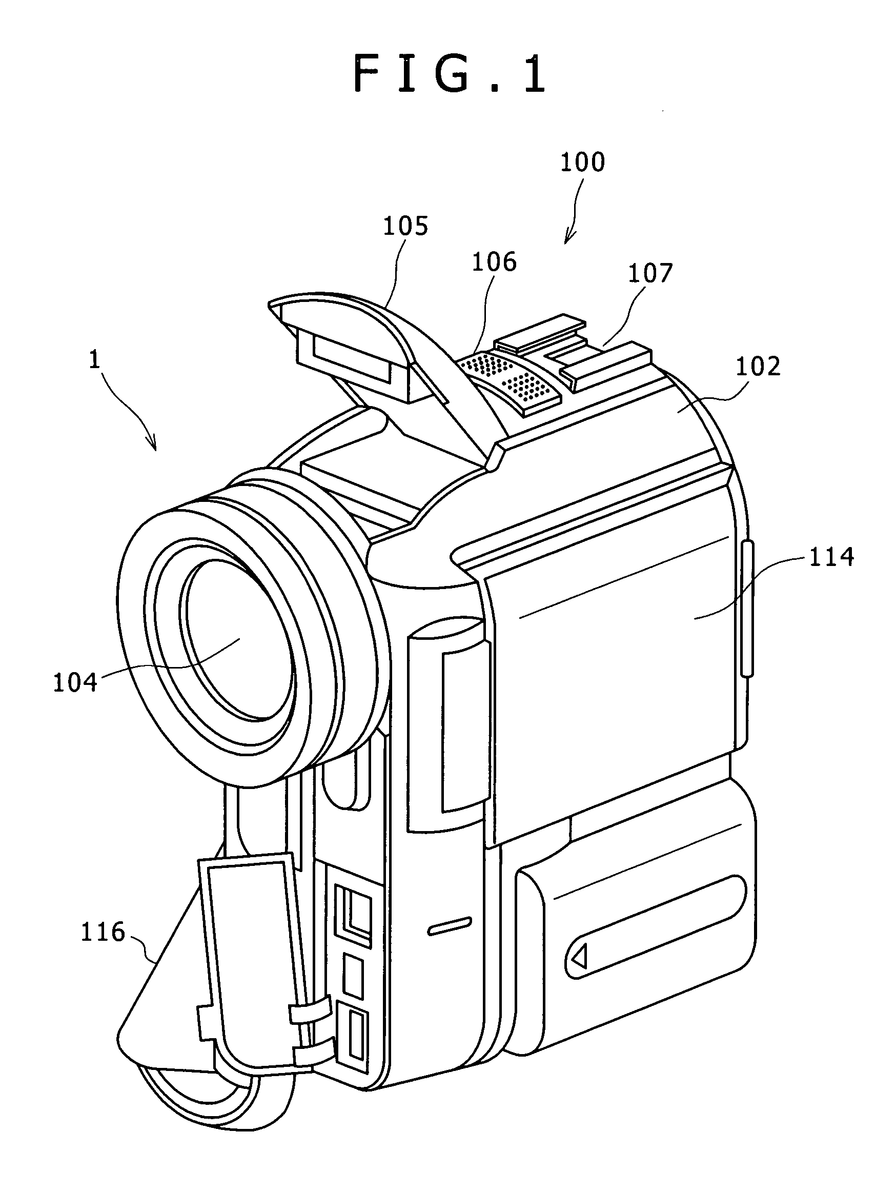
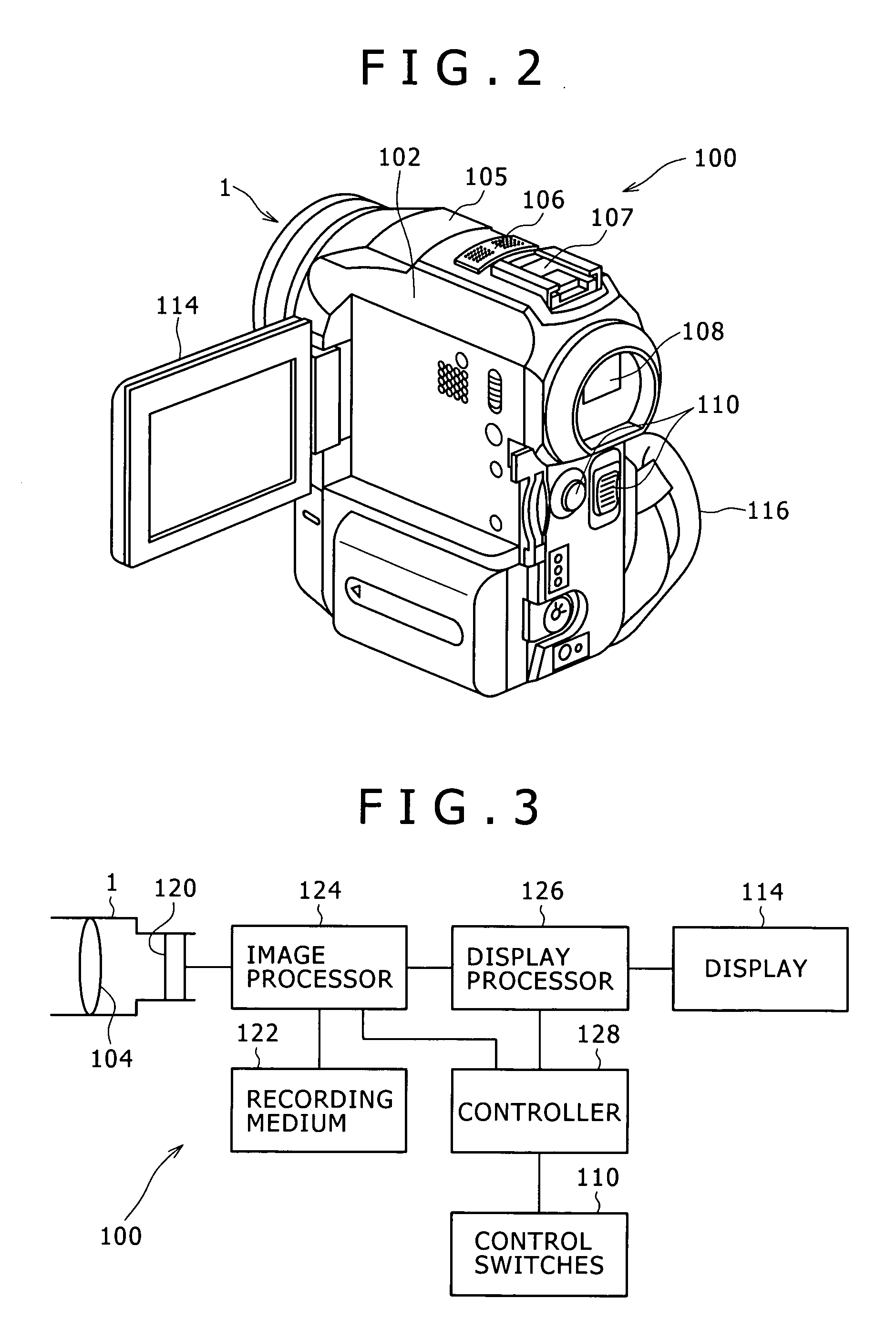
[0025]FIG. 1 is a perspective view, as viewed from front, of an image capturing apparatus according to Embodiment 1, FIG. 2 is a perspective view, as viewed from rear, of the image capturing apparatus, and FIG. 3 is a block diagram of the image capturing apparatus.

[0026] As shown in FIGS. 1 and 2, an image capturing apparatus 100 according to the present embodiment includes a video camera having a case 102 as an outer housing.

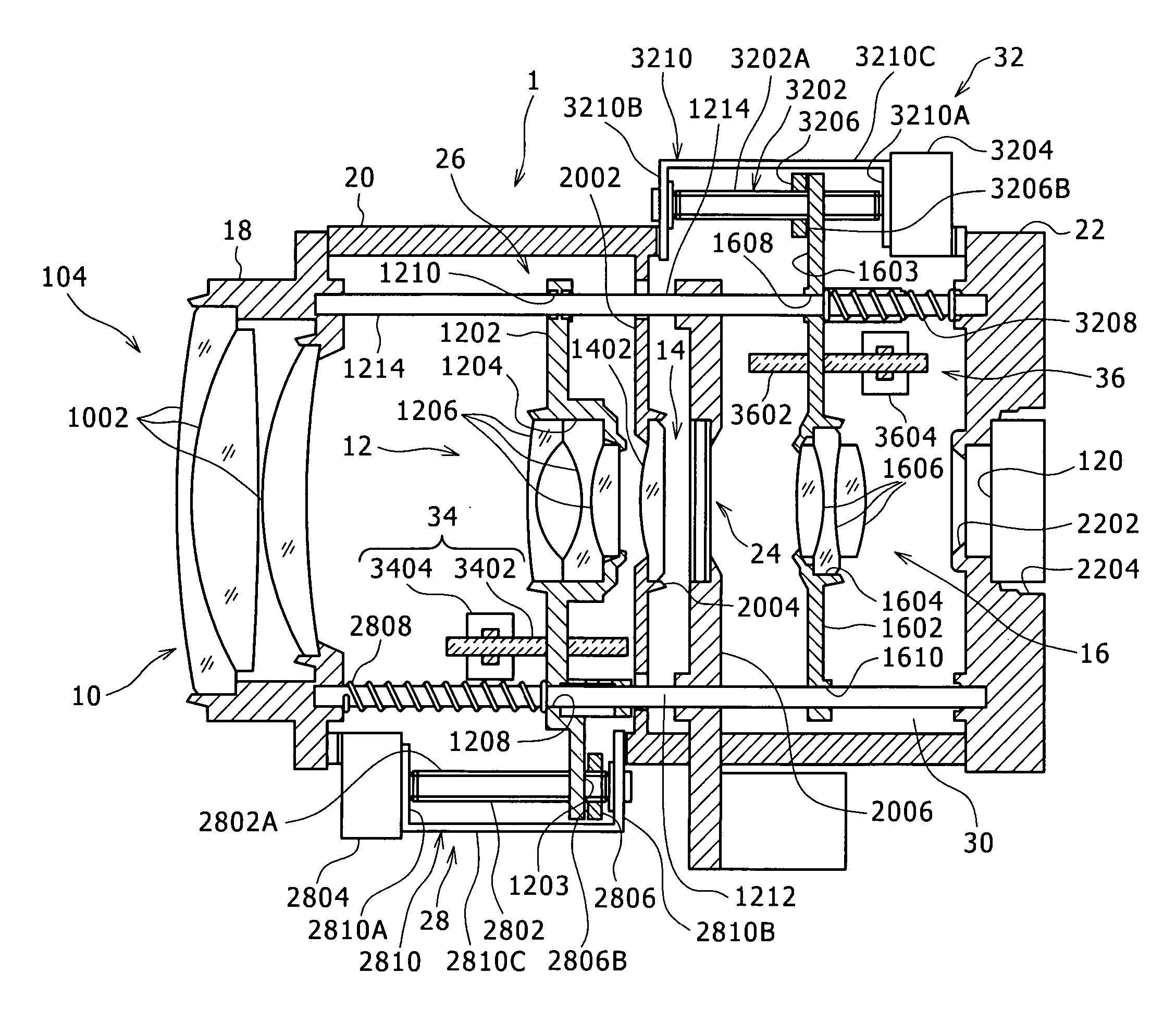
[0027] A lens barrel 1 accommodating an imaging optical system 104 is mounted on an upper portion of a front surface of the case 102. On an upper surface of the case 102, there are disposed a pop-up flash unit 105 for emitting assistive light when capturing images, a microphone 106 for recording sounds, and a shoe 107 for mounting accessories, which are successively arranged in the order named from a front portion to a rear portion of the upper surface.

[0028]...

embodiment 2

[0119] Embodiment 2 will be described below.

[0120] Embodiment 2 differs from Embodiment 1 in that the imaging optical system includes a collapsible lens.

[0121]FIGS. 9A through 9C are cross-sectional views of a collapsible lens. FIG. 9A shows the collapsible lens in a collapsed state. FIG. 9B shows the collapsible lens in a wide-angle state. FIG. 9C shows the collapsible lens in a telephoto state. FIG. 10 is a cross-sectional view of a movable lens. Those portions and parts shown in FIGS. 9A through 9C and FIG. 10 which are identical to those according to Embodiment 1 are denoted by identical reference characters, and will not be described in detail below.

[0122] As shown in FIGS. 9A through 9C, the imaging optical system housed in the lens barrel 1 is of a three-group configuration including a first group lens 50, a second group lens 52, and a third group lens 54 that are successively arranged in the order named from the front side toward the rear side.

[0123] The lens barrel 1 pe...


PUM


Abstract

There are provided a lens barrel assembly and an image capturing apparatus which are advantageous to increase the feeding accuracy for a movable lens and to reduce the size of a lens barrel.
Second group position detecting means 34 is provided for generating positional data corresponding to the position of a second group lens 12. The angular displacement of a second group motor 2804 is controlled in order to equalize the position of the second group lens 12 along the optical axis to a target position based on the positional data supplied from the second group position detecting means 34. If the positional data remains unchanged for a certain period of time while the second group motor 2804 is in rotation, then it is judged that the second group lens 12 is forcibly stopped against movement and the second group motor 2804 is immediately de-energized.

Description

TECHNICAL FIELD [0001] The present invention relates to a lens barrel assembly and an image capturing apparatus. BACKGROUND ART [0002] Image capturing apparatus such as digital still cameras, digital video cameras, etc. have a lens barrel assembly including an imaging optical system assembled in a lens barrel. [0003] The lens barrel assembly has a movable lens disposed in the lens barrel and movable along an optical axis thereof, but nonrotatable about the optical axis, and an actuating mechanism for moving the movable lens along the optical axis. The actuating mechanism includes an internally threaded member mounted on the movable lens, an external threaded member threaded in the internally threaded member and extending parallel to the optical axis, and urging means such as a helical spring or the like for urging the movable lens in the longitudinal direction of the external threaded member (see, for example, Japanese Patent Laid-open No. 2002-287002). [0004] The movable lens has a...

Claims


Application Information

Patent Timeline
IPC IPC(8): G02B13/16G02B7/04G02B7/08H04N5/225
CPCH04N5/2254G02B7/08H04N23/55
Inventor MAKII, TATSUO
Owner SONY CORP
Why Eureka
Try Eureka