Multifunction camera assembly for a computer
a computer and multi-functional technology, applied in the field of computer video cameras, can solve the problems of user inconvenience and inconvenience, and achieve the effects of convenient use, increased functions, and convenient adjustment of relative position and angl
- Summary
- Abstract
- Description
- Claims
- Application Information
AI Technical Summary
Benefits of technology
Problems solved by technology
Method used
Image

Examples
first embodiment
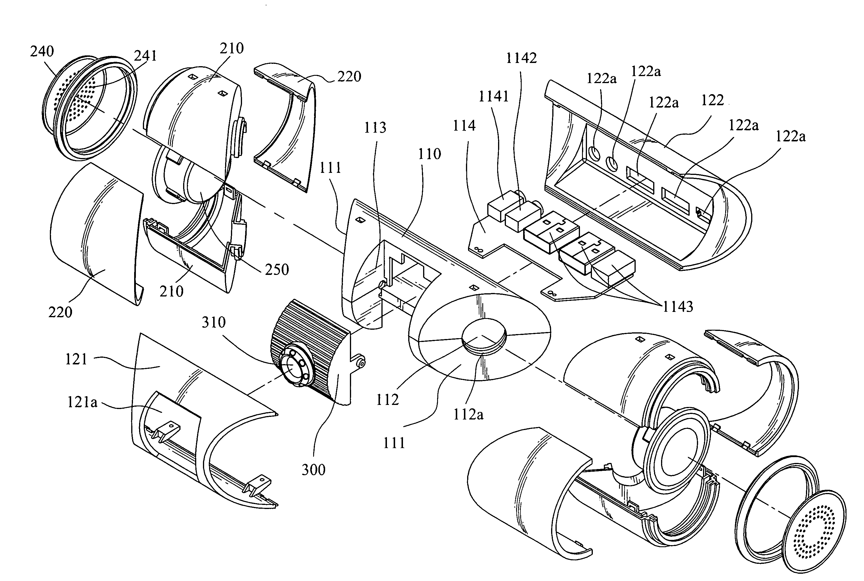
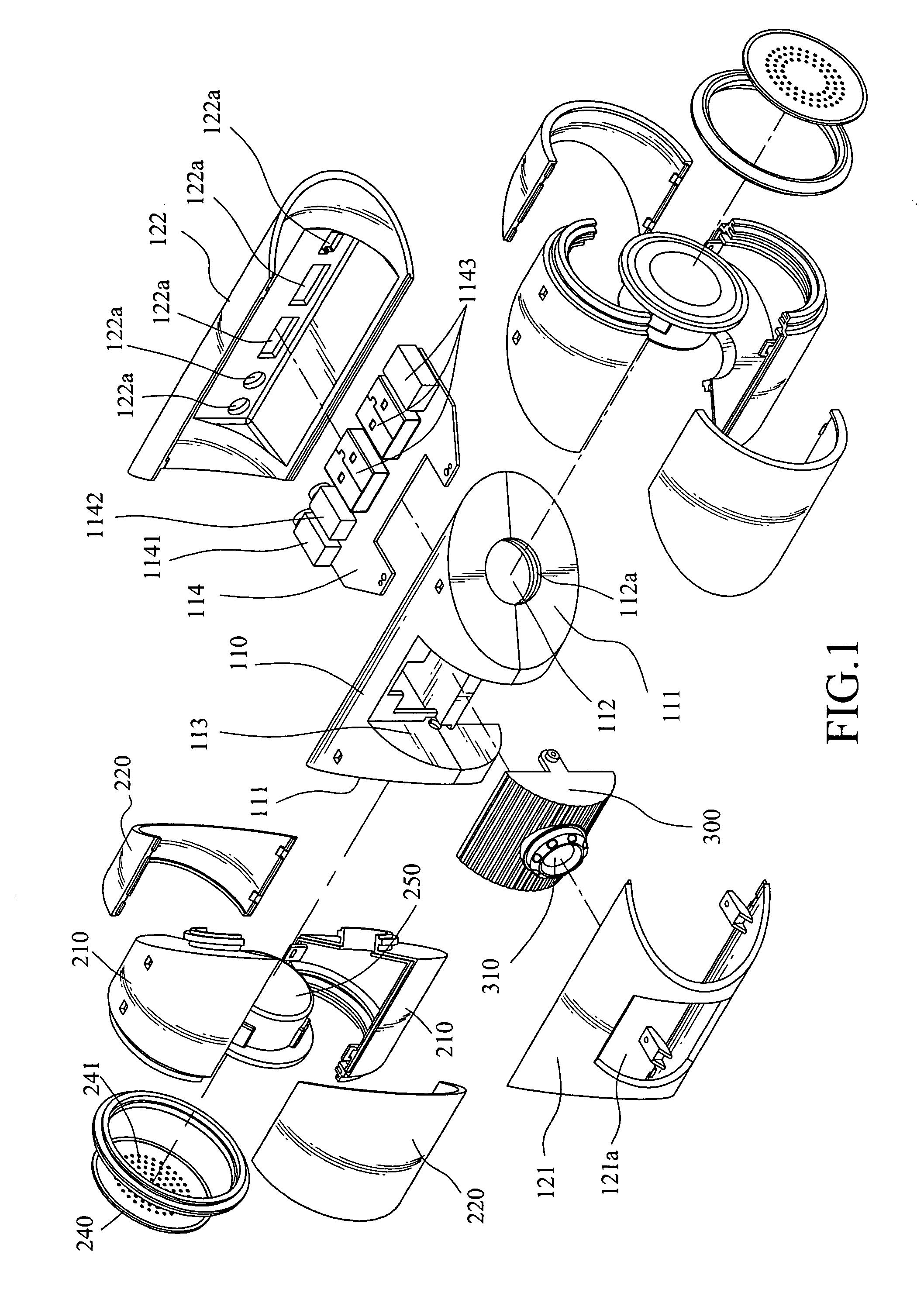
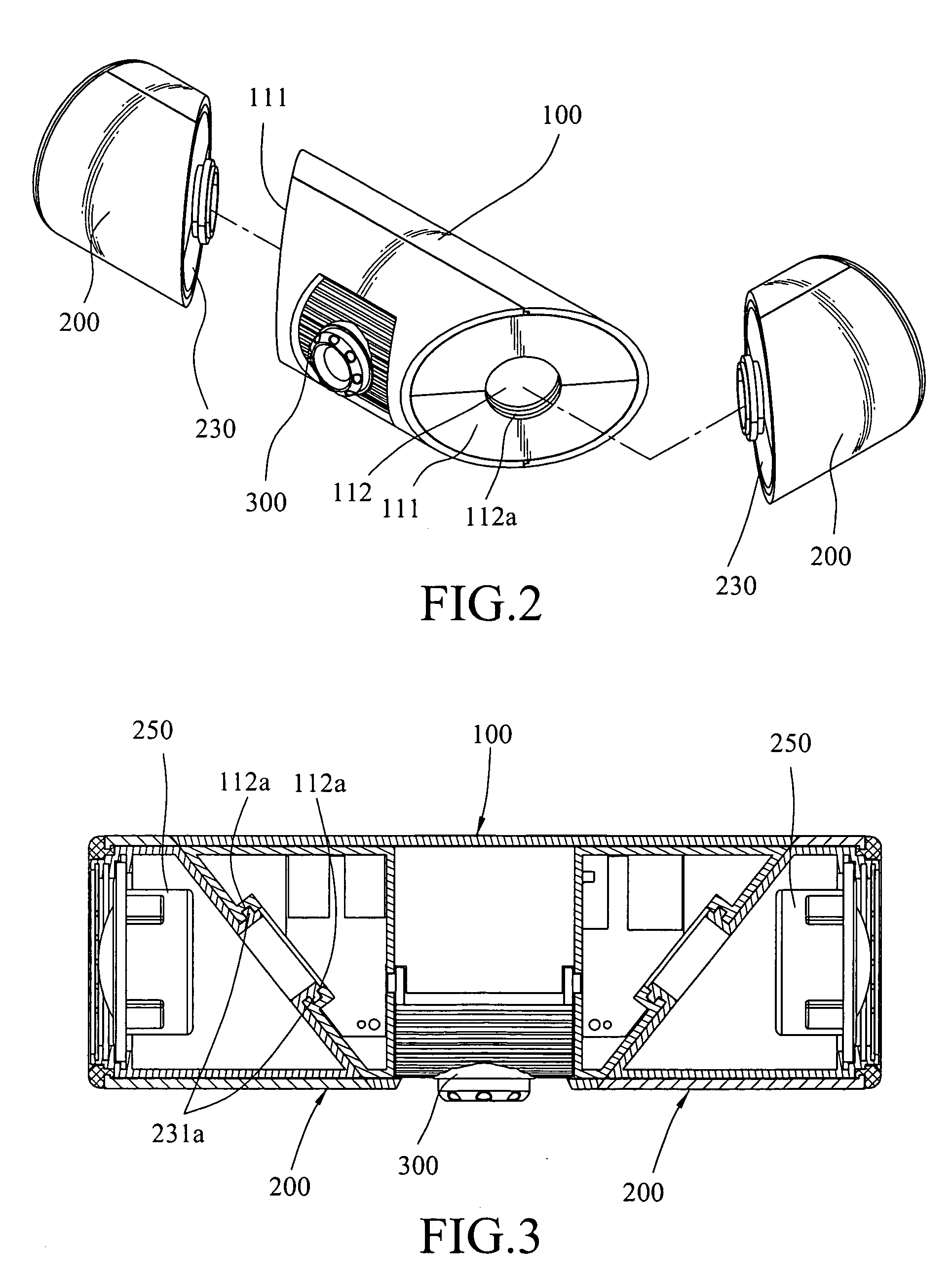
[0023]Referring to FIG. 1, FIG. 2, and FIG. 3, a multifunction video camera assembly according to the present invention is provided. The multifunction video camera assembly includes a computer video camera 100 and two computer peripherals 200, wherein the computer video camera 100 and the computer peripherals 200 are column shaped. However, the shape is not limited to this, and other various shapes also can be used. Also, in the present embodiment, each of the computer peripherals 200 is a speaker, and it is also may be a microphone, a wireless receiver, a USB hub, a fingerprint identification device, a card reader, a ion generator, and the like.
[0024]The computer video camera 100 includes an inner frame 110, two housings 121 and 122, and a video camera unit 300, wherein the inner frame 110 is provided with a first bevel surface 111 respectively on both ends of the computer video camera 100, and the first bevel surface 111 forms an inclined angle with the central axis of the compute...
third embodiment
[0030]Referring to FIG. 8, the preset invention is provided. A speaker unit 250 is disposed in one of the two computer peripherals 200 to form a speaker; an audio receiver unit 270 is disposed in the other computer peripheral 200, such that the computer peripheral 200 becomes a microphone. Therefore, the multifunction camera assembly is provided with the functions of image capturing, sound broadcasting, audio receiving, and the like. Meanwhile, since the computer peripheral 200 can rotate relative to the image camera 100, the directions of the speaker unit 250 and the audio receiver unit 270 can be changed, such that both of them have preferred effects for receiving audio and broadcasting sounds.
fourth embodiment
[0031]Referring to FIG. 9, the present invention is provided. A speaker unit 250 is disposed in one of the two computer peripherals 200 to form a speaker; a fingerprint identification module 280 is disposed in the other computer peripheral 200, such that the computer peripheral 200 becomes a fingerprint identification device through this fingerprint identification module 280, thereby a user can carry out fingerprint identification, to protect the computer and to provide different authorization of different users for operating the computer.
PUM
 Abstract
Description
Claims
Application Information
 - R&D
- Intellectual Property
- Life Sciences
- Materials
- Tech Scout
- Unparalleled Data Quality
- Higher Quality Content
- 60% Fewer Hallucinations
Browse by: Latest US Patents, China's latest patents, Technical Efficacy Thesaurus, Application Domain, Technology Topic, Popular Technical Reports.
© 2025 PatSnap. All rights reserved.Legal|Privacy policy|Modern Slavery Act Transparency Statement|Sitemap|About US| Contact US: help@patsnap.com