
Thin-film magnetic head having near-field-light-generating portion with trapezoidal end

a magnetic head and trapezoidal end technology, applied in the field of thin film magnetic heads, can solve the problems of increasing the coercive force of the magnetic recording medium, reducing the magnetic stability of the recording bit, and limiting the write field intensity of the magnetic head for writing data signals against the coercive for

Active Publication Date: 2007-08-02
TDK CORPARATION
View PDF7 Cites 73 Cited by
  • Summary
  • Abstract
  • Description
  • Claims
  • Application Information

AI Technical Summary

Benefits of technology

[0019]Therefore, it is an object of the present invention to provide a thin-film magnetic head for a heat-assisted magnetic recording which can perform a reliable writing immediately only on a desired track by applying a near-field light to a desired position and range, an HGA provided with this thin-film magnetic head and a magnetic recording apparatus provided with this HGA.
[0020]And it is another object of the present invention to provide a thin-film magnetic head in which the generation efficiency of near-field light is improved, and therefore a sufficient amount of near-field light can be applied to a desired position and range, an HGA provided with this thin-film magnetic head and a magnetic recording apparatus provided with this HGA.
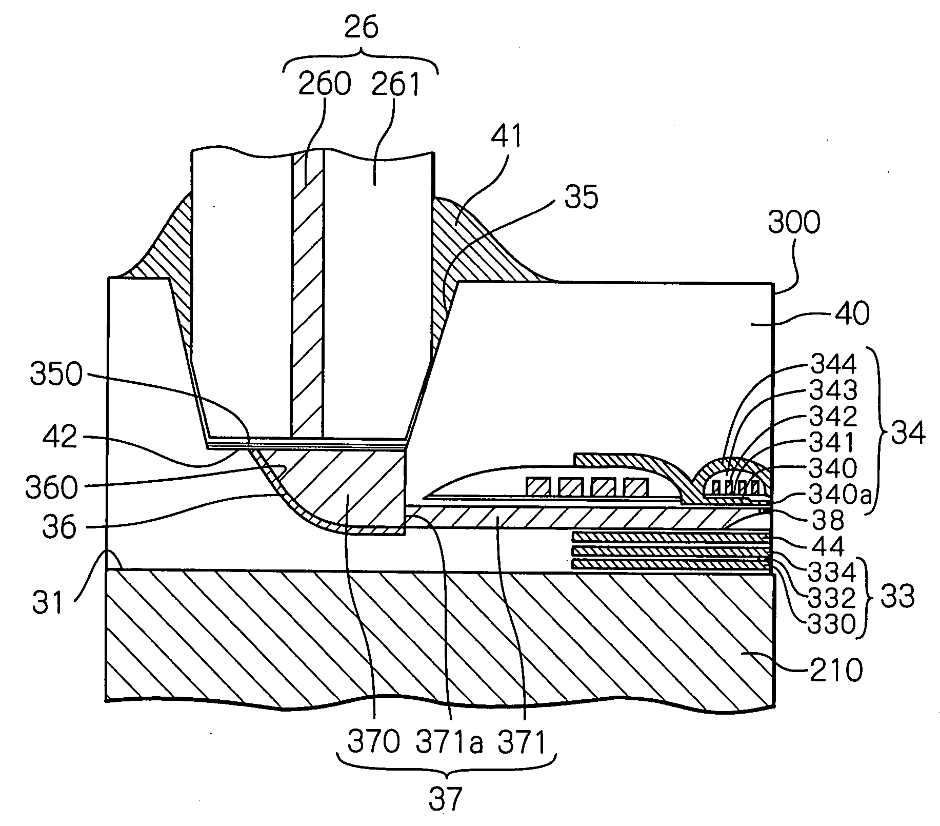
[0023]By using the above-described position and shape of the generation end, the neighborhood of the shorter edge of the generation end, which is the main heating portion, becomes much close to the pole end of the main magnetic pole layer, which is the writing portion. Therefore, the error in the track width direction of the positioning between the generation end and the pole end can be suppressed. Further, in the actual heat-assisted writing operations, just after the near-field light generated from the neighborhood of the shorter edge is applied to a part of the recording layer, the write field generated from the pole end is applied to the heated part. That is, the writing can be reliably performed almost without a pause just after the part of the recording layer is heated, which prevents the write error due to the inadequacies of the heated part and heating timing and enables the heat-assisted write operation to be performed reliably and stably.
[0029]The offset configuration enables the generation end to fall almost into the track width that is mainly determined by the longer edge on the trailing side of the pole end, in every case that the head is positioned above the outer track and above the inner track. As a result, the near-field light has almost no possibility to cover the inner and outer adjacent tracks, which can prevent an unwanted writing or erasing to the adjacent tracks due to a skew angle of the head.

Problems solved by technology

However, a problem is likely to occur that the size decrease causes thermal stability of the magnetization of the recording bit to be degraded.
However, the increase in the KU causes the increase in coercive force of the magnetic recording medium.
On the other hand, the write field intensity of the magnetic head for writing data signals against the coercive force is limited by the amount of the saturation magnetic flux density of the soft-magnetic pole material of the head.
Therefore, the head cannot write data signals to the medium when the coercive force exceeds the write field limit.
However, in these techniques, there is some possibility of writing error such as an insufficient writing to a desired track or an unwanted writing or erasing to the adjacent tracks, depending on the range and timing of the near-field light application during heat-assisting operation.
Depending on the position and shape of the reaching end, there are some cases to miss sufficient writing to a track to be written because of insufficient heating of the track.
Further, when writing at rather intervals after applying the near-field light, the coercive force of the medium may exceed the writing limit of the write field due to the cooldown of the medium.
In this case, a desired writing cannot be performed.
Furthermore, in the case that the near-field light covers the adjacent tracks, an unwanted writing may be performed on the adjacent tracks.
However, in the past, no clear and adequate measures against these problems have been suggested.
Therefore, depending on the position and shape of the end of the main magnetic pole, an unwanted writing or erasing may be performed to the adjacent tracks.
However, this technique is not intended for a thin-film magnetic head with a main magnetic pole for perpendicular magnetic recording.
Thus, in the past, no clear and adequate measures against this problem have been suggested.

Method used


Image

  • Thin-film magnetic head having near-field-light-generating portion with trapezoidal end
  • Thin-film magnetic head having near-field-light-generating portion with trapezoidal end
  • Thin-film magnetic head having near-field-light-generating portion with trapezoidal end

Examples


Embodiment Construction

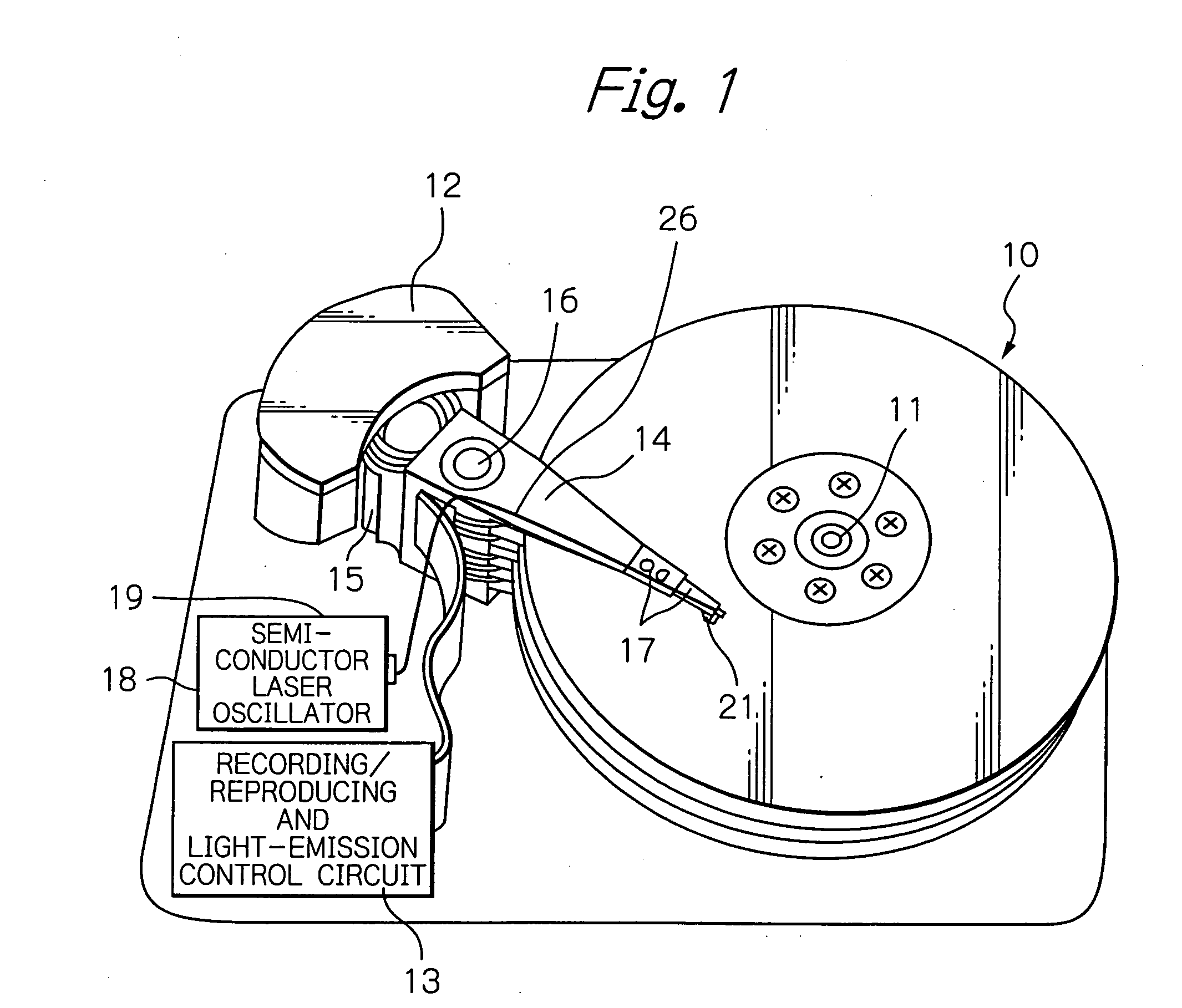
[0049]FIG. 1 shows a perspective view schematically illustrating a major portion of an embodiment of the magnetic disk drive apparatus according to the present invention.

[0050]In FIG. 1, reference numeral 10 indicates a plurality of magnetic disks (magnetic recording media) for a perpendicular magnetic recording, rotating around a rotational axis of a spindle motor 11, 12 indicates an assembly carriage device for positioning a thin-film magnetic head (slider) 21 for the perpendicular magnetic recording on a track, and 13 indicates a recording / reproducing and light-emission control circuit for controlling read / write operations of the thin-film magnetic head and for controlling a semiconductor laser oscillator 18 that is a light source for generating a laser light used for heat-assisting operations, respectively.

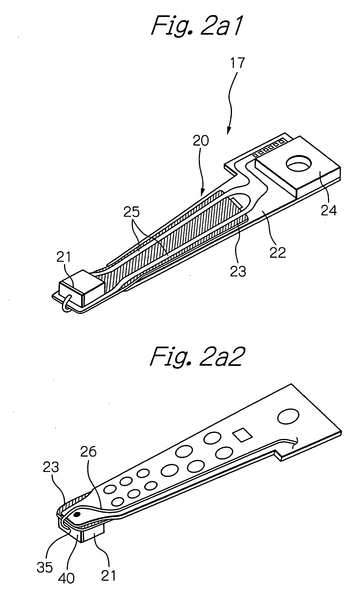
[0051]The assembly carriage device 12 is provided with a plurality of drive arms 14. These drive arms 14 are rotatable around a pivot bearing axis 16 by means of a voice coil ...


PUM


Abstract

A thin-film magnetic head for a heat-assisted magnetic recording which can perform a reliable writing immediately only on a desired track by applying a near-field light to a desired position and range is provided. The head comprises: an electromagnetic coil element for writing data signals, having a pole end reaching a head end surface; and a near-field-light-generating portion for heating a portion of a magnetic recording medium during write operation by generating a near-field light, having a generation end reaching the head end surface and provided adjacent to the pole end and in the leading side of the pole end, and a shape of the generation end on the head end surface being a trapezoid with a shorter edge on the trailing side, or being a triangle with an apex on the trailing side and with a bottom on the leading side.

Description

PRIORITY CLAIM[0001]This application claims priorities from Japanese patent application No. 2006-20441, filed on Jan. 30, 2006 and Japanese patent application No. 2006-25387, filed on Feb. 2, 2006, which are incorporated herein by reference.BACKGROUND OF THE INVENTION[0002]1. Field of the Invention[0003]The present invention relates to a thin-film magnetic head for reading and writing data signals, a head gimbal assembly (HGA) with the thin-film magnetic head and a magnetic recording apparatus with the HGA. Especially, the present invention relates to a thin-film magnetic head for writing data signals by a heat-assisted perpendicular magnetic recording technique using a near-field light, an HGA with the thin-film magnetic head and a magnetic recording apparatus with the HGA.[0004]2. Description of the Related Art[0005]Recently, in a magnetic recording apparatus such as a magnetic disk drive apparatus, a thin-film magnetic head is strongly required to further improve its performance ...

Claims


Application Information

Patent Timeline
IPC IPC(8): G11B5/147G11B5/02
CPCG11B5/314G11B2005/0021G11B5/3967
Inventor SHIMAZAWA, KOJITAGAMI, KATSUMICHI
Owner TDK CORPARATION
Learn More