High efficiency fluid mover

a turbomachinery and high-efficiency technology, applied in the direction of positive displacement liquid engines, piston pumps, liquid fuel engines, etc., can solve the problems of large decrease in computer efficiency and reduced battery life, and achieve the effect of increasing static pressur

Inactive Publication Date: 2007-08-02
INTEL CORP
View PDF15 Cites 58 Cited by
  • Summary
  • Abstract
  • Description
  • Claims
  • Application Information

AI Technical Summary

Benefits of technology

[0016] In another embodiment, a rotor for transferring momentum to or from a fluid in response to rotor rotation comprises a rigid, self-reinforcing, stacked matrix of passages having first ends distributed over a fluid inlet surface of the rotor. The first ends of the passages defining an open cross sectional area for fluid flow that is at least 70% of the flui...

Problems solved by technology

Experience has shown that effective fan and blower designs for large machines which are proportionately scaled down to produce a small machine to fit in a laptop ...

Method used


Image

  • High efficiency fluid mover
  • High efficiency fluid mover
  • High efficiency fluid mover

Examples


Embodiment Construction

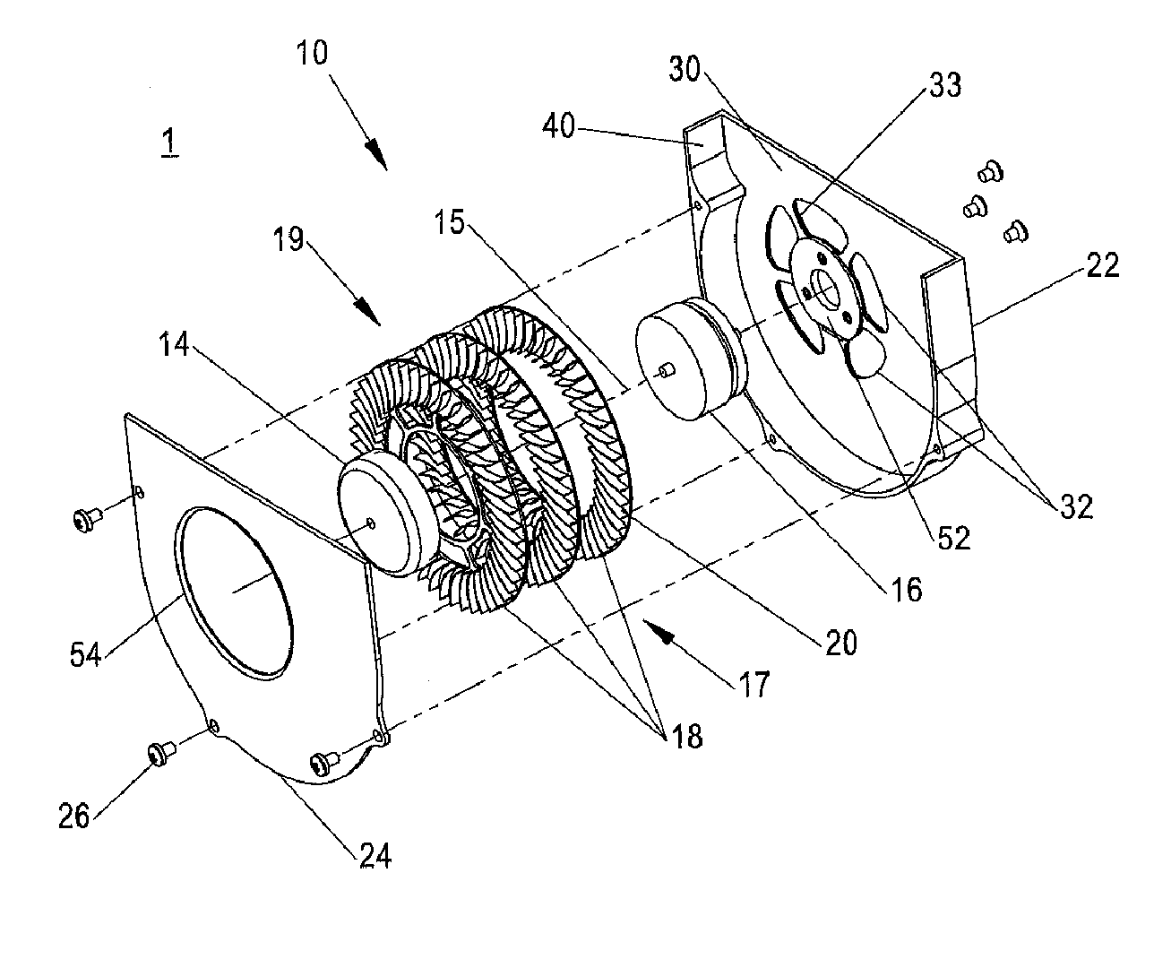
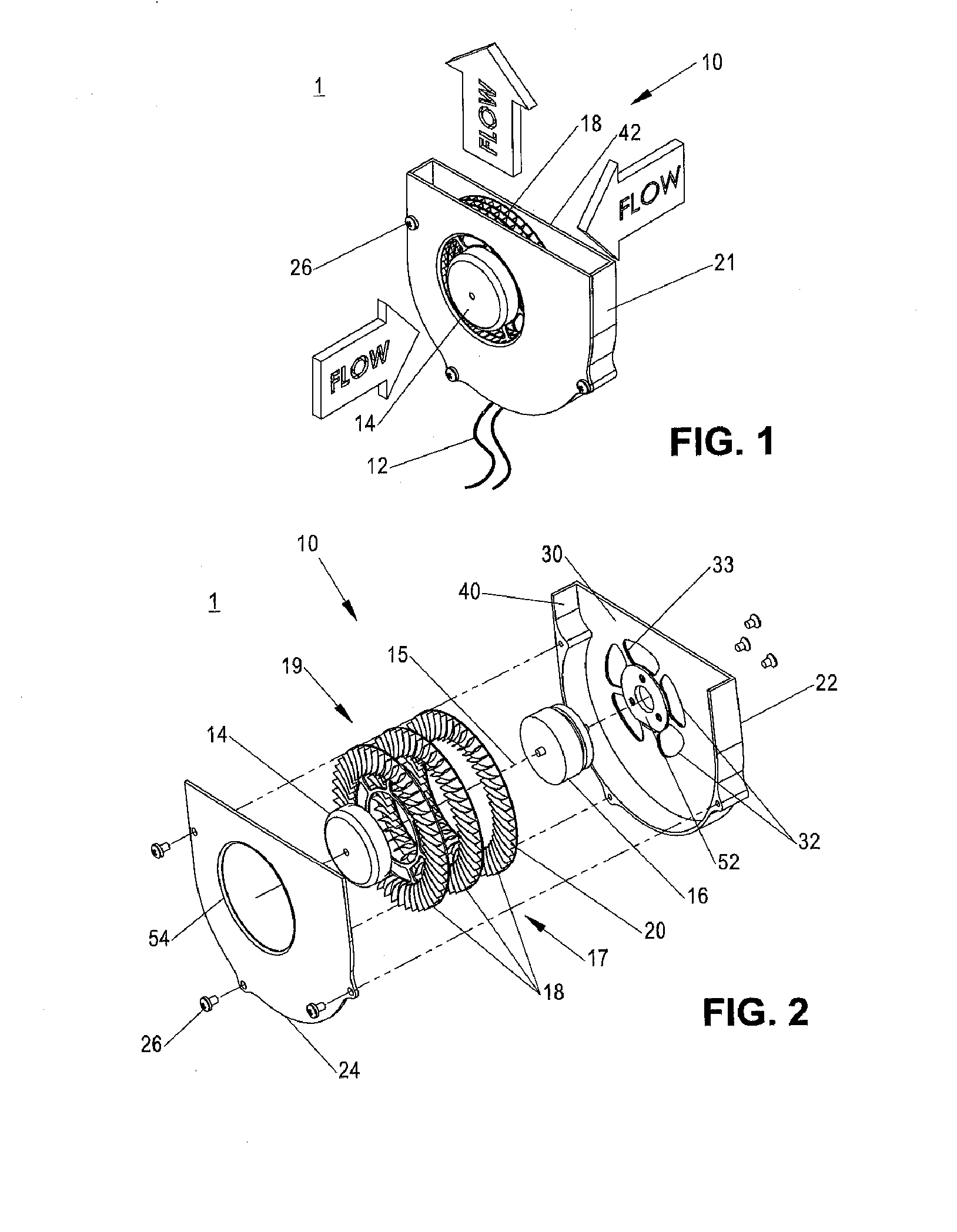
[0041]FIGS. 1 and 2 are respectively a perspective view and an exploded view of fluid momentum transfer device 1 comprising a radial fluid mover 10 constructed in accordance with an embodiment of the present invention. The fluid referred to with respect to FIGS. 1 and 2 is air. Air is a fluid which is commonly moved. However, the description of air movement comprises a description of movement of other fluids as well. While in the present illustration a momentum transfer device 1 is discussed which transfers momentum to fluid, embodiments could also be provided which transfer momentum from fluid. The momentum transfer device 1 could comprise a turbine in which momentum is transferred from air to a rotor. In FIG. 1, air flow direction is indicated by arrows. The radial blower 10 has a power line 12 which enters a housing 21. The housing 21 may conveniently be a square or rectangular housing or may closely follow a curved interior shape of an outlet fluid flow collector. The blower 10 ...


PUM


Abstract

A fluid mover includes a rotor to transfer momentum with a fluid when operated at a given volumetric flow rate through the rotor. The rotor includes a plurality of enclosed passages to transfer momentum in or out of the fluid as the fluid passes through the enclosed passages in response to rotation of the rotor. The passages are formed with a cross sectional shape and cross sectional dimensions along their entire length sufficient to establish and maintain laminar flow of the fluid along the entire length of the enclosed passages when the fluid is passing through the rotor at the given volumetric flow rate. The fluid mover also includes a housing having at least one inlet and at least one outlet for the fluid.

Description

CROSS REFERENCE TO RELATED APPLICATIONS [0001] This application claims priority to U.S. Provisional Application 60 / 739,316, filed by Theodore B. Hill and Charles C. Hill on Nov. 23, 2005, and to U.S. Non-Provisional application Ser. No. 11 / 335,284, filed by Theodore B. Hill and Charles C. Hill on Jan. 19, 2006, both commonly assigned to Hill Engineering. This application is also a continuation-in-part of U.S. Non-Provisional application Ser. No. 11 / 335,284.BACKGROUND OF THE INVENTION [0002] 1. Field of the Invention [0003] The subject of the present invention relates to fluid-moving turbomachinery. [0004] 2. Description of the Related Art [0005] Turbomachinery comprises rotating, fluid flow dynamic devices for transferring momentum into or out of the flowing fluid. The present subject matter relates to turbines driven by moving fluid as well as powered rotors which move fluid. Often, the fluid under consideration will be air. However, the considerations discussed here and below appl...

Claims


Application Information

Patent Timeline
IPC IPC(8): H05K7/20
CPCF04D29/2255F04D29/703F04D29/681F04D29/281F04D17/167
Inventor POKHARNA, HIMANSHUBAUGH, ERICDISTEFANO, ERICKU, JASONMONGIA, RAJIVNISHI, YOSHIFUMIHILL, THEODORE B.HILL, CHARLES C.
Owner INTEL CORP
Why Eureka
Try Eureka