Distance measuring system

a distance measurement and distance technology, applied in the field of distance measuring apparatus, can solve the problems of inefficient light use of line averaging, reduced light collection of objective lens, and ineffective technique on specular surfaces

Inactive Publication Date: 2007-08-02
MARSHALL DANIEL R
View PDF13 Cites 5 Cited by
  • Summary
  • Abstract
  • Description
  • Claims
  • Application Information

AI Technical Summary

Benefits of technology

[0011] Embodiments of the present invention include a light source emitting a collimated reference beam of light. Any portion of the reference beam on one side of an optical axis is blocked by a knife-edge element. The remaining outgoing reference beam travels to the target surface, where it is reflected as an incoming reference beam on the opposite side of the optical axis. The incoming reference beam is diverted by the reflecting surface of the knife-edge element to a photodetector that generates an electronic output signal according to the position of the incoming reference beam on the surface of the photodetector. The signal generally corresponds to the distance from the objective lens of the microscope to the target surface and may be used to generate an output signal. The knife-edge element enables the incoming reference beam to generally follow the path that would have been taken by the blocked portion of the outgoing reference beam.
[0012] In some embodiments of the invention, a scanning mirror controllably deflects the outgoing reference beam and the incoming reference beam. Because the two reference beams generally follow the same optical path, the deflection of the incoming reference beam compensates for the deflection of the outgoing reference beam, so that the position of the incoming reference beam on the surface of the photodetector is generally independent of the deflection of the outgoing reference beam made by the scanning mirror. In this way, the measured distance is unaffected by scanning the outgoing reference beam along the target.
[0014] Thus, the distance measurement system may be used to directly measure the topology of the target surface, to correct focus by commanding the precision mechanism to displace the target surface according to the focus output signal, or to enhance the depth properties of the image itself.

Problems solved by technology

However, line averaging inefficiently uses light because the focus line typically diverges strongly after reflection, thus reducing the amount of light collected by the objective lens.
This technique is particularly inefficient on specular surfaces, meaning mirror-like surfaces.
Also, aberrations, particularly astigmatism aberrations, can cause wave front errors that degrade or bias the focus output signal.
Moreover, because the amount of astigmatism introduced by the toric lens is fixed, the user cannot choose a length of line that is appropriate to the specific application, nor can computer-based image processing systems direct the focus sensing spot to a specific location.
However, this type of system is relatively complex, is often expensive, and is prone to measurement errors caused by artifacts introduced by the rotating mirror.
Furthermore, a precision multi-faceted mirror scanner is generally relatively expensive and difficult to produce.
Polygon scanning systems have typically not been used in focus sensing systems for reasons of cost, complexity and size.

Method used


Image

  • Distance measuring system
  • Distance measuring system
  • Distance measuring system

Examples


Embodiment Construction

[0022] While the invention is susceptible of various modifications and alternative constructions, certain illustrated embodiments thereof have been shown in the drawings and will be described below in detail. It should be understood, however, that there is no intention to limit the invention to the specific form disclosed; on the contrary, the invention is to cover all modifications, alternative constructions, and equivalents falling within the spirit and scope of the invention as defined in the claims.

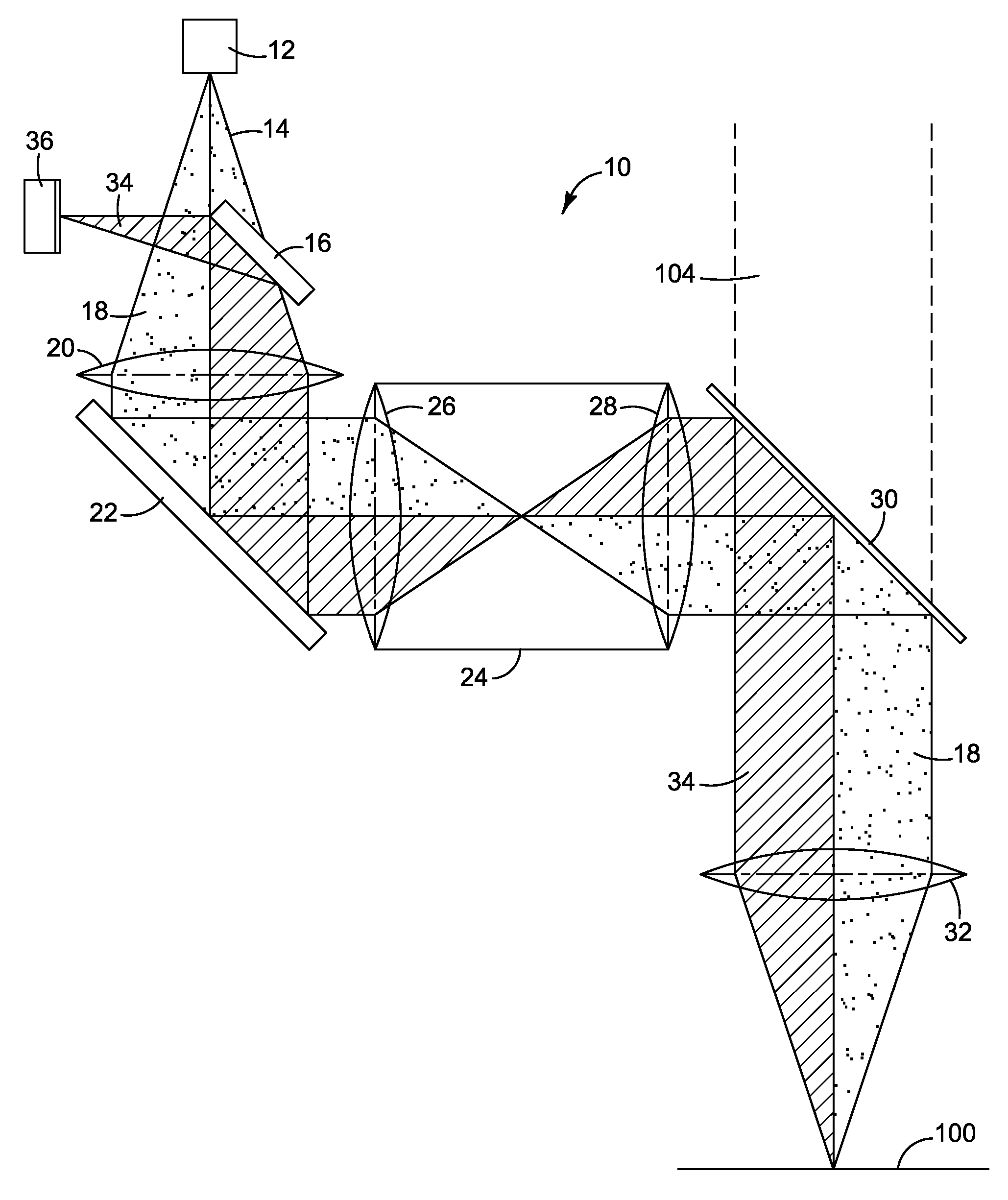
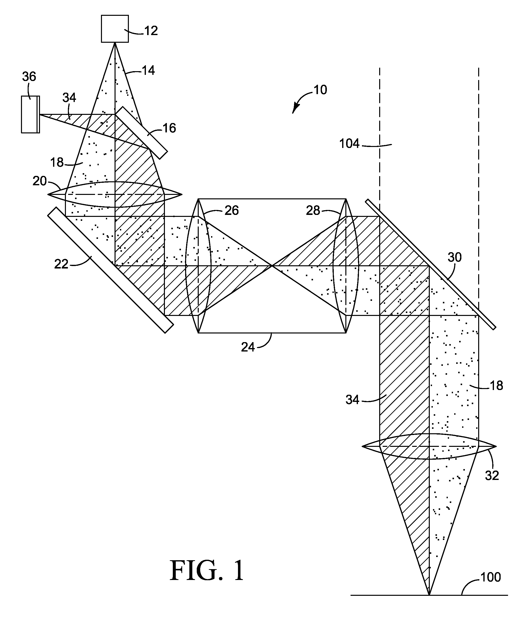
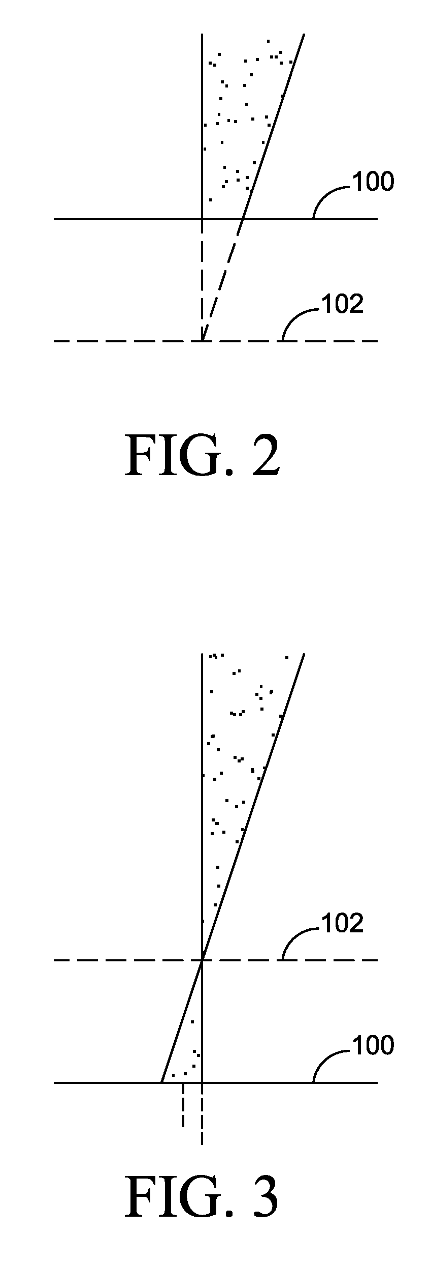
[0023] Microscopes are used to examine minute objects by enlarging an image. In a classical compound microscope, the microscope has an objective lens and an eyepiece lens that define an image beam passing through the lenses. The image beam is formed from light reflected from a target surface. The target surface is in focus when located at the in-focus region, a distance away from the objective lens defined by the optical characteristics of the combination of the objective and eyepiec...


PUM

PropertyMeasurementUnit
anglesaaaaaaaaaa
distanceaaaaaaaaaa
displacementaaaaaaaaaa

Abstract

A distance measuring device capable of being used in microscopes or other optical systems. Embodiments of the invention employ one or more scanning mirrors to scan a reference beam over a target to be inspected. The reference beam is returned and detected by a photodetector. The reference beam may be created by using a knife-edge element which allows the outgoing reference beam and incoming reference beam to follow the same path so that the apparent motion of the spot on the target surface is not detected by the photodetector. The photodetector generates an electronic signal corresponding to the displacement of the target away from the ideal focal point. The electronic signal may be used to drive a servomechanism to displace either the target or the microscope objective lens to bring the target in focus.

Description

CROSS-REFERENCE TO RELATED APPLICATIONS [0001] This application is a divisional application of application Ser. No. 11 / 312,034, filed Dec. 20, 2005, entitled Distance Measuring System, which is pending and incorporated herein by this reference.FIELD OF THE INVENTION [0002] The invention relates generally to an apparatus for measuring distance to a surface, and more particularly to measuring distance to a target surface through an optical system for purposes that include adjusting focus in an optical system. BACKGROUND OF THE INVENTION [0003] A microscope is an optical instrument that has historically employed two or more lenses to make enlarged images of minute objects. In the so-called compound microscope, an objective lens is placed near a target to be viewed and the user views an image of the target through an eyepiece lens. In many installations, the eyepiece lens is replaced with a camera, often a digital camera using a charge coupled device as an imaging element. [0004] Micros...

Claims


Application Information

Patent Timeline
Patent Type & Authority Applications(United States)
IPC IPC(8): G02B27/40G11B7/00
CPCG01S7/4812G02B21/0048G01S17/48G01S7/4817
Inventor MARSHALL, DANIEL R.
Owner MARSHALL DANIEL R
Why Eureka
Try Eureka