
Sound packet reproducing method, sound packet reproducing apparatus, sound packet reproducing program, and recording medium

a sound packet and reproducing technology, applied in multiplex communication, data switching networks, instruments, etc., can solve the problems of small delay in voice communication, awkward two-way voice communication quality, and inability to reproduce sound, so as to reduce voice communication delay, save costs, and save costs

Inactive Publication Date: 2007-08-02
NIPPON TELEGRAPH & TELEPHONE CORP
View PDF7 Cites 38 Cited by
  • Summary
  • Abstract
  • Description
  • Claims
  • Application Information

AI Technical Summary

Benefits of technology

[0009] An object of the present invention is to provide a reproducing method and apparatus for audio packets that has improved functionality by using insertion and removal of pitch waveforms. MEANS TO SOLVE PROBLEMS
[0024] By applying the present invention to communication in which audio signals are communicated in real time over a packet communication network where a large amount of packet arrival delay jitter occurs, the consumption of an audio data stream can be steadily controlled to adjust the number of packets in a receiving buffer regardless of the presence or absence of voice, therefore an optimum control of the receiving buffer can be performed according to changes in the conditions (jitter time) of the communication network. Consequently, voice communication without audible discontinuities in speech and with minimized voice communication delay can be implemented. Most packet communication networks are designed to tolerate a certain degree of jitter in order to save costs. The use of the present invention also has the effect of saving costs relating to network use because audible discontinuities do not occur without using a high-quality network where jitter caused by the network itself is small.

Problems solved by technology

There is a problem that substantial variations in packet arrival time arise depending on the conditions of the communication network and, as a result, packets may not arrive within a time limit (time equivalent to one frame length) and discontinuities may occur in reproduced sound.
A problem is that if the number of packets to be stored in the receiving buffer is chosen to be a large value, large packet arrival jitter can be absorbed but a large amount of delay between reception of a packet and reproduction of sound, namely communication delay, occurs, which may make the quality of two-way voice communications awkward.
On the other hand, if the number of packets to be stored in the receiving buffer is chosen to be a small value, delay in voice communication will be small but audible discontinuities will be more likely to occur when packet arrival jitter occurs.
That is, there is a trade-off between communication delay and the likelihood of audible discontinuities.
However, this method cannot provide control using the receiving buffer if the frequency of non-voice segment occurrences is significantly low or a non-voice segment does not occur over a long period of time.
Although degradation of audio quality can be reduced by inserting or removing pitch waveforms, the sound quality of reproduced sound can be degraded to an undesirable extent because the insertion and removal of pitch-period waveforms are performed on a series of frames until the number of packets stored in the buffer reaches a value between the upper and lower thresholds.
Moreover, because the upper and lower thresholds are fixed, sudden changes in jitter cannot be managed and consequently packet loss may occur.

Method used


Image

  • Sound packet reproducing method, sound packet reproducing apparatus, sound packet reproducing program, and recording medium
  • Sound packet reproducing method, sound packet reproducing apparatus, sound packet reproducing program, and recording medium
  • Sound packet reproducing method, sound packet reproducing apparatus, sound packet reproducing program, and recording medium

Examples


first embodiment

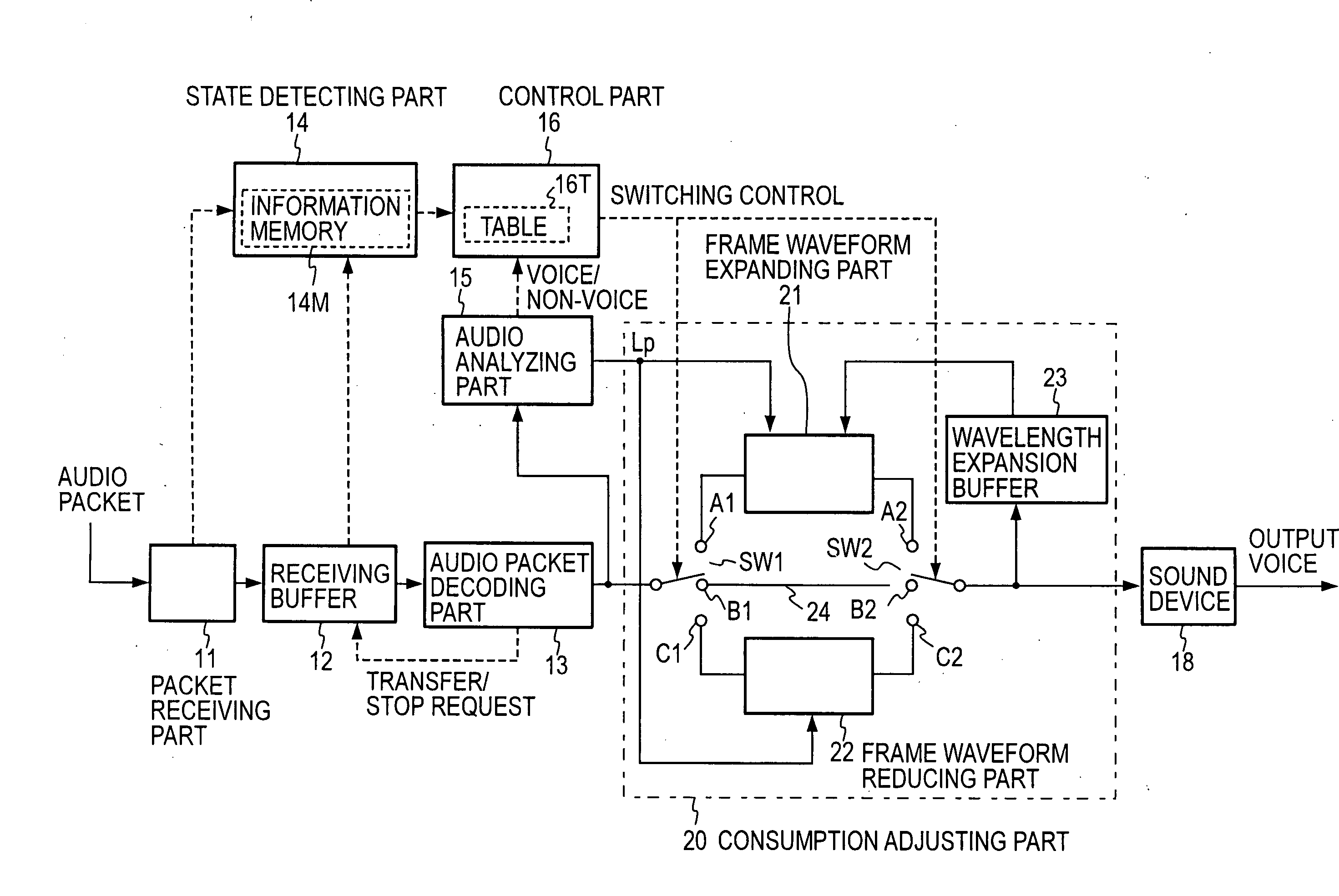
[0048]FIG. 3 shows an exemplary configuration of an audio signal receiving part according to the present invention, which includes a packet receiving part 11, a receiving buffer 12, an audio packet decoding part 13, a state detecting part 14, an audio analyzing part 15, a control part 16, a consumption adjusting part 20, and a sound device 18. The packet receiving part 11 receives audio packets from a communication network, stores them in the receiving buffer 12, and provides their arrival times and timestamps to the state detecting part 14. An audio packet contains an audio code generated by dividing an audio signal into time units having a given length (typically 10 to 20 milliseconds or so) called frames and converting the audio signal in the time unit by using an audio encoding technique, and a timestamp (corresponding to a frame number) indicating the order in time of the generation of the packet. A typical audio encoding technique is G.711 which is an ITU-T (International Tele...

second embodiment

[0127] In the audio analyzing part 15 shown in FIG. 6, the frame power Pf is compared against the fixed threshold Pth to determine whether a decoded audio signal in the current frame is in a voice segment or a non-voice segment. This configuration is advantageously simple. However, if a decoded audio signal contains high-level background noise (such as the hum of an air conditioner, babble in an office, or street noise), it may be difficult to precisely determine whether a frame is in a voice segment or a non-voice segment. FIG. 19 shows a configuration which alleviates the problem by taking into consideration background noise in voice segment / non-voice segment determination.

[0128] In the configuration of the audio analyzing part 15 shown in FIG. 19, a dynamic power threshold calculating part 150 is provided in addition to the components shown in FIG. 6, and a pitch correlation calculating part 158 performs pitch analysis to obtain the pitch length Lp and also obtain a pitch correl...

third embodiment

[0132] While determination is made whether each frame is in a voice segment or non-voice segment in the first and second embodiments, further determination is made in this embodiment as to whether a voice segment is a voiced sound segment or an unvoiced sound segment and whether a non-voice segment is a background noise segment or a silence segment. Thus, each frame is identified as any of the four types of segments, namely, voiced sound, unvoiced sound, background noise, and silence segments, and a consumption adjusting part 20 is controlled on the basis of the identification. A configuration of an audio analyzing part 15 used for this is shown in FIG. 20.

[0133] In the configuration of the audio analyzing part 15 shown in FIG. 20, a pitch correlation value r is provided also to a segment determining part 154 in the configuration shown in FIG. 19, both a dynamic power threshold Pd and a fixed power threshold Pth are used as the power thresholds in the segment determining part 154, ...


PUM


Abstract

The present invention prevents a receiving buffer from becoming empty by: storing received packets in the receiving buffer; detecting the largest arrival delay jitter of the packets and the buffer level of the receiving buffer by a state detecting part; obtaining an optimum buffer level for the largest delay jitter using a predetermined table by a control part; determining, based on the detected buffer level and the optimum buffer level, the level of urgency about the need to adjust the buffer level; expanding or reducing the waveform of a decoded audio data stream of the current frame decoded from a packet read out of the receiving buffer by a consumption adjusting part to adjust the consumption of reproduction frames on the basis of the urgency level, the detected buffer level, and the optimum buffer level.

Description

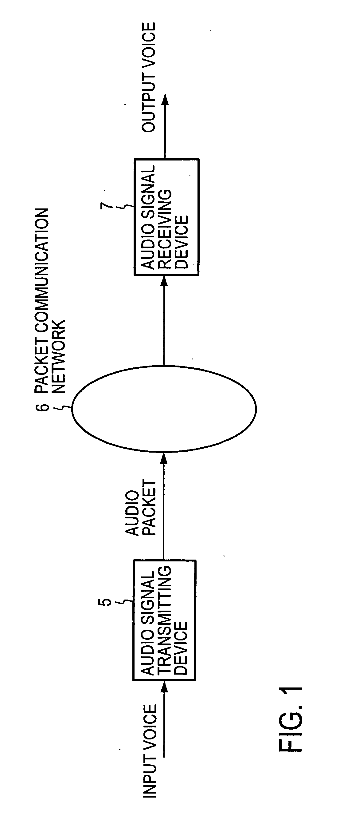
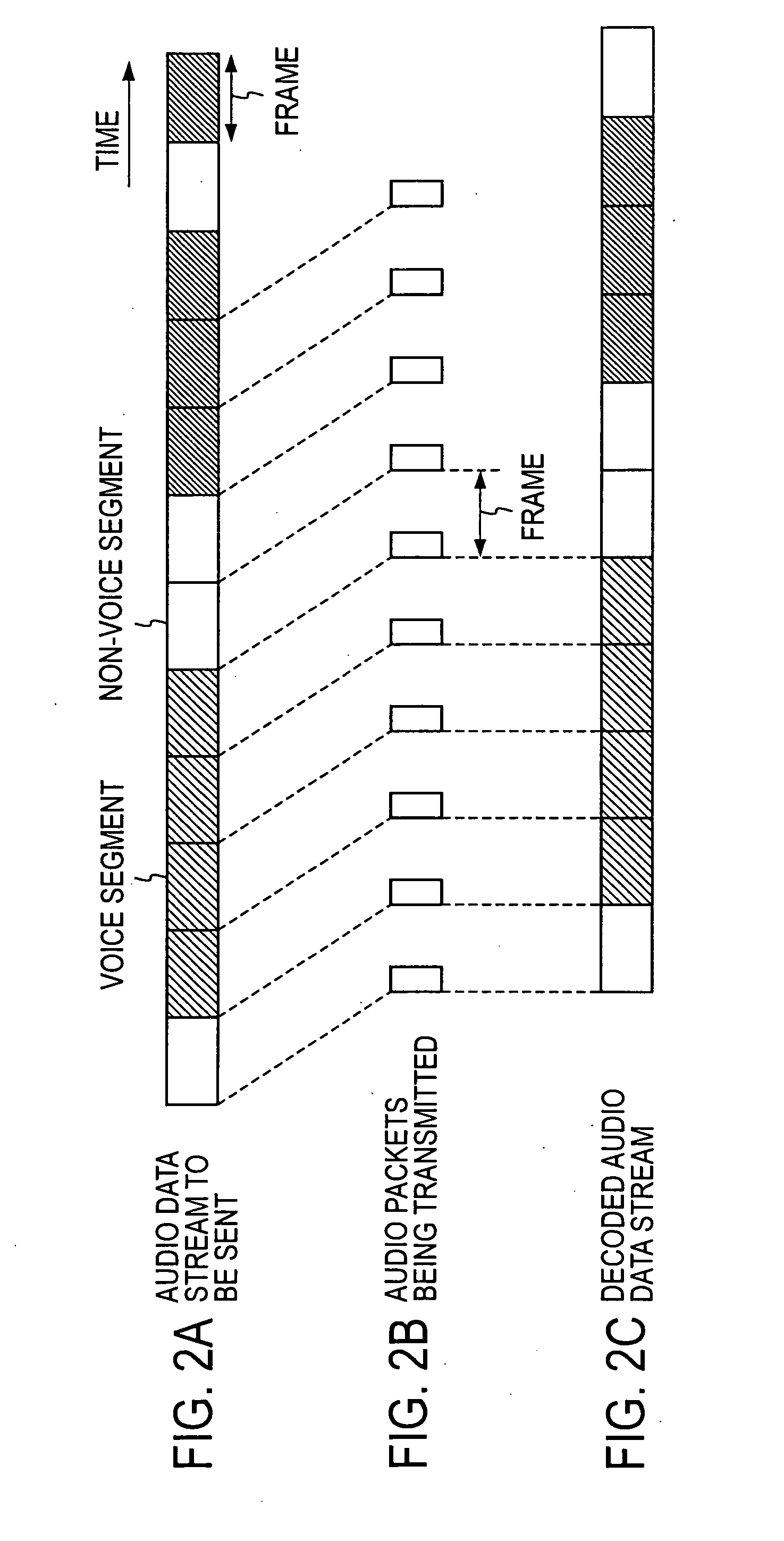
TECHNICAL FIELD [0001] The present invention relates to a reproducing method, apparatus, and program, and a recording medium having the program recorded thereon, used for reproducing a sound signal such as digitized voice and music (hereinafter collectively called an audio signal) sent through a packet communication network such as the Internet with a stable quality at a receiving end. BACKGROUND ART [0002] Services that use Voice over IP technology (hereinafter simply referred to as audio packet communication) to transmit or receive audio signals are becoming widespread. FIG. 1 shows an outline of such a service. An input audio signal is converted into audio packets in an audio signal transmitting device 5 and sent to a packet communication network 6. An audio signal receiving device 7 identifies and receives audio packets destined to it, and decodes them to output speech. [0003]FIG. 2 shows the relationship between an audio data stream to be sent and audio packets. FIG. 2A shows t...

Claims


Application Information

Patent Timeline
Patent Type & Authority Applications(United States)
IPC IPC(8): H04L12/56H04J3/06G10L19/00G10L19/005G10L25/78
CPCG10L19/005H04J3/0632G10L21/04
Inventor OHMURO, HITOSHIMORI, TAKESHIHIWASAKI, YUSUKEKATAOKA, AKITOSHI
Owner NIPPON TELEGRAPH & TELEPHONE CORP
Learn More