
Mimo-ofdm system using eigenbeamforming method

a beam forming and immo technology, applied in the field of multi-input multiple output (mimo)orthogonal frequency division multiplexing (ofdm) system, can solve the problems of large amount of feedback information, method does not satisfy diversity gain, and difficult to apply beam forming method, so as to reduce the amount of feedback information

Active Publication Date: 2007-08-02
ELECTRONICS & TELECOMM RES INST
View PDF8 Cites 209 Cited by
  • Summary
  • Abstract
  • Description
  • Claims
  • Application Information

AI Technical Summary

Benefits of technology

[0010] It is an advantage of the present invention to reduce an amount of feedback information for eigenbeam forming in an OFDM system.

Problems solved by technology

The method does not require feedback information since the method uses reciprocity of the channels; however the method does not satisfy diversity gain since the beam forming vector does not include the instantaneous channel variation.
Thus, it is difficult to apply the beam forming method when the number of transmit antennas is large or the speed of the mobile station is high.
In this case, the amount of the feedback information becomes very much larger than that of the single subcarrier, and the feedback information provides a severe burden to the system.

Method used


Image

  • Mimo-ofdm system using eigenbeamforming method
  • Mimo-ofdm system using eigenbeamforming method
  • Mimo-ofdm system using eigenbeamforming method

Examples


Embodiment Construction

[0021] In the following detailed description, only the preferred embodiment of the invention has been shown and described, simply by way of illustration of the best mode contemplated by the inventor(s) of carrying out the invention. As will be realized, the invention is capable of modification in various obvious respects, all without departing from the invention. Accordingly, the drawings and description are to be regarded as illustrative in nature, and not restrictive. To clarify the present invention, parts which are not described in the specification are omitted, and parts for which similar descriptions are provided have the same reference numerals.

[0022] In a MIMO system with a single carrier wherein the number of transmit antennas is L and the number of receive antennas is M, a received signal vector r(q) at the qth symbol period is as in the following Equation 1.

r(q)=√{square root over (γ)}H(q)ws(q)+n(q)   [Equation 1]

[0023] Here, r is a transmitting signal to noise ratio, r...


PUM


Abstract

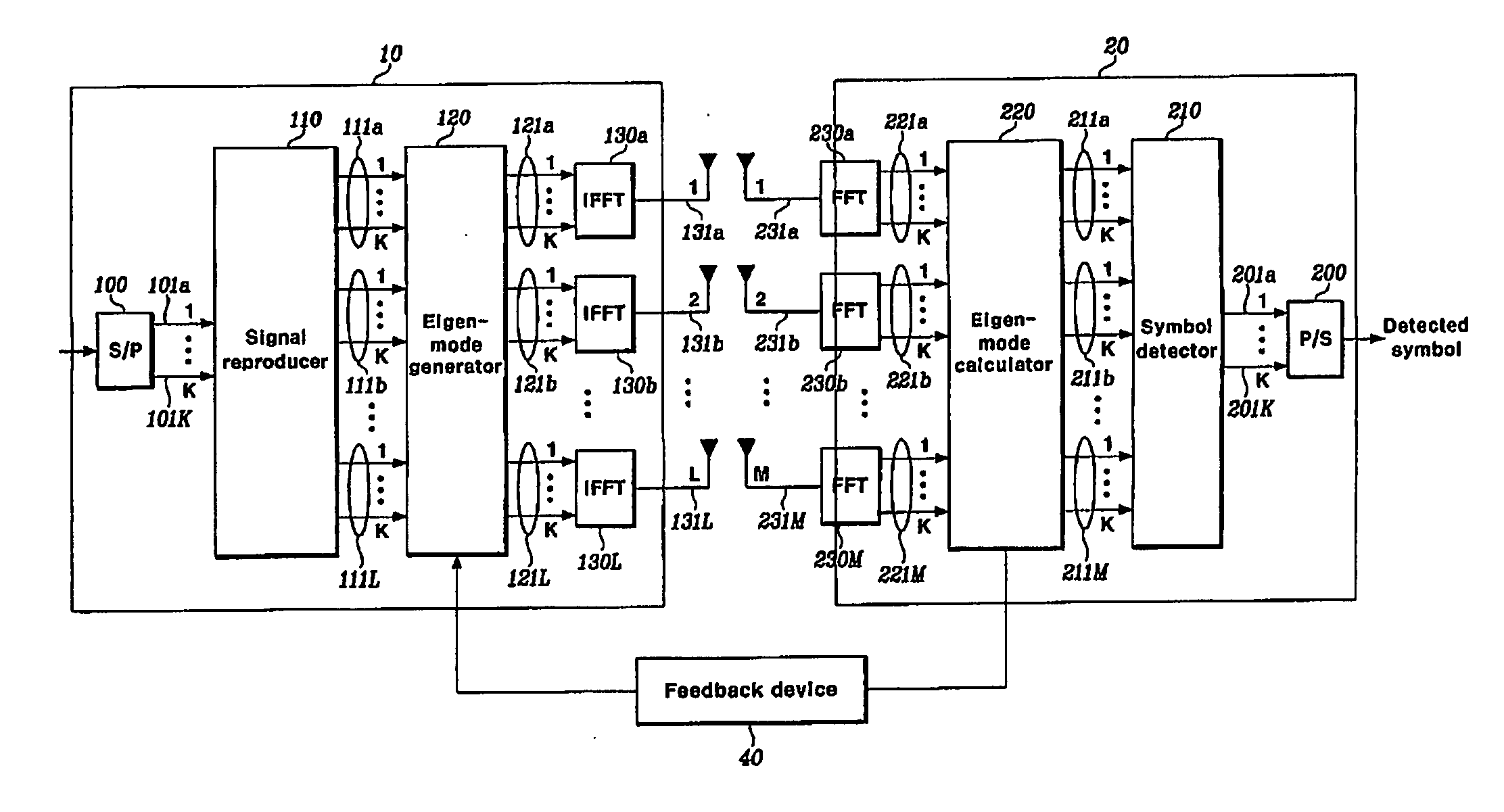
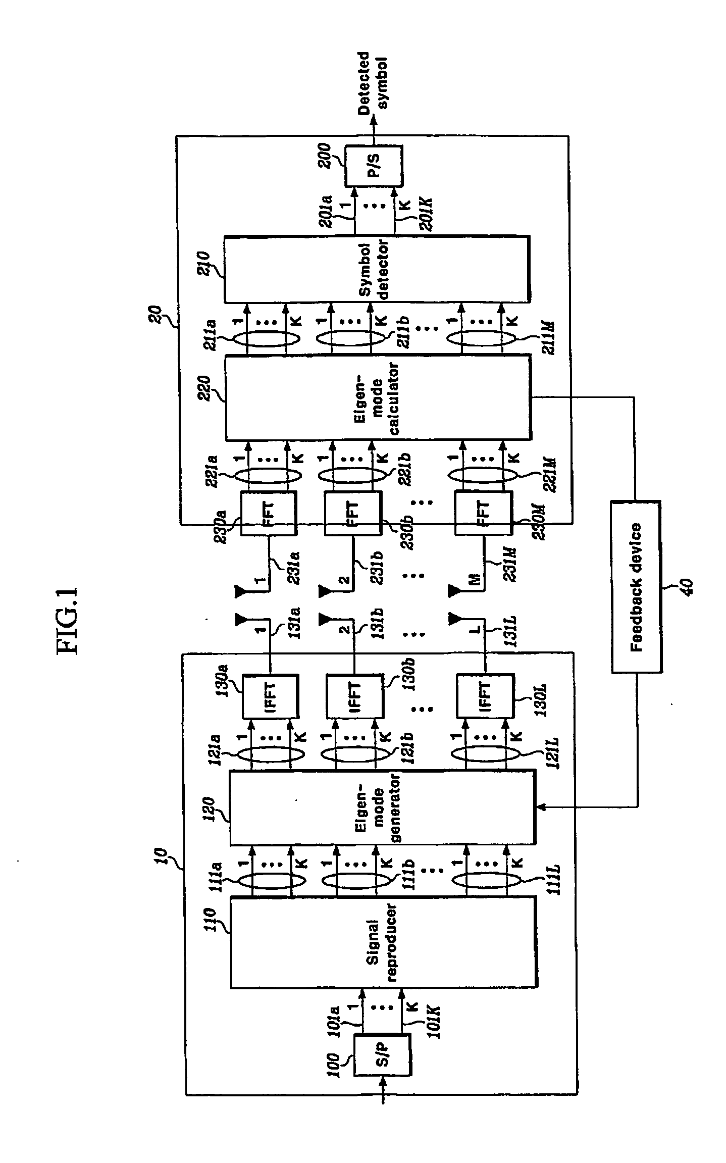
Disclosed is a MIMO-OFDM system, wherein the transmitter comprises a serial / parallel converter for converting continuously inputted symbols of the number of subcarriers to K parallel signals; a signal reproducer for reproducing K parallel signals by the number of transmit antennas L an eigenmode generator for generating eigenbeam of the reproduced signals outputted from the signal reproducer at each subcarrier, on the basis of Nf eigenbeam forming vectors which are fed back long-term and information of a best eigenbeam forming vector at each subcarrier which is fed back short-term, through the feedback device; and a plurality of inverse Fourier converters for receiving the signals outputted from the eigenmode generator and generating an OFDM symbol.

Description

CROSS REFERENCE TO RELATED APPLICATION [0001] This application claims priority to and the benefit of Korea Patent Application Nos. 2003-98216 and 2003-98217 filed on Dec. 27, 2003 in the Korean Intellectual Property Office, the entire content of which is incorporated herein by reference. BACKGROUND OF THE INVENTION [0002] (a) Field of the Invention [0003] The present invention relates to a Multiple Input Multiple Output (MIMO)-Orthogonal Frequency Division Multiplexing (OFDM) system. More specifically, the present invention relates to a MIMO-OFDM system using eigenbeam forming in a downlink. [0004] (b) Description of the Related Art [0005] A beam forming method has been used to obtain the antenna array gain to improve performance. Also, the beam forming method can be used to use a space domain in a downlink channel of a MIMO system. Generally, a base station is required to have instantaneous channel information in a downlink to apply a closed-loop downlink beam forming method. In a ...

Claims


Application Information

Patent Timeline
IPC IPC(8): H04L27/00H04K1/10H04L27/28H04B7/04H04J99/00H04L1/06H04L25/03
CPCH04B7/0417H04B7/0634H04B7/065H04B7/066H04L1/06H04L2025/03426H04L25/03343H04L27/2626H04L27/2647H04L2025/03414H04L1/0693
Inventor CHOI, IN-KYEONGKIM, SEONG-RAGKWON, DONG-SEUNGCHOI, JIN-HO
Owner ELECTRONICS & TELECOMM RES INST
Learn More