
Image processing apparatus

a technology of image processing and image signals, applied in the field of image processing apparatuses, can solve the problems of code generation variability, code underflow, etc., and achieve the effect of improving image quality

Inactive Publication Date: 2007-08-02
CANON KK
View PDF18 Cites 10 Cited by
  • Summary
  • Abstract
  • Description
  • Claims
  • Application Information

AI Technical Summary

Benefits of technology

The present invention provides an image processing apparatus that can improve image quality while controlling the amount of codes. It includes a quantizing unit, a coding unit, an activity detecting unit, a quantization-scale determining unit, a changing unit, a filling level detecting unit, and a control unit. The activity detecting unit detects the activity of the input moving image signal and the quantization-scale determining unit determines the quantization scale based on the amount of variable length codes output from the coding unit. The changing unit changes the quantization scale based on the activity detected by the activity detecting unit and the filling level detected by the filling level detecting unit. The control unit controls the changing unit to reduce the change in the quantization scale when the filling level decreases. This invention can improve image quality while controlling the amount of codes.

Problems solved by technology

However, if the quantization step is weighted using the activity of an image without reference to the amount of codes actually generated, the amount of generated codes may vary and an underflow of coded data may occur.

Method used


Image

  • Image processing apparatus
  • Image processing apparatus
  • Image processing apparatus

Examples


first exemplary embodiment

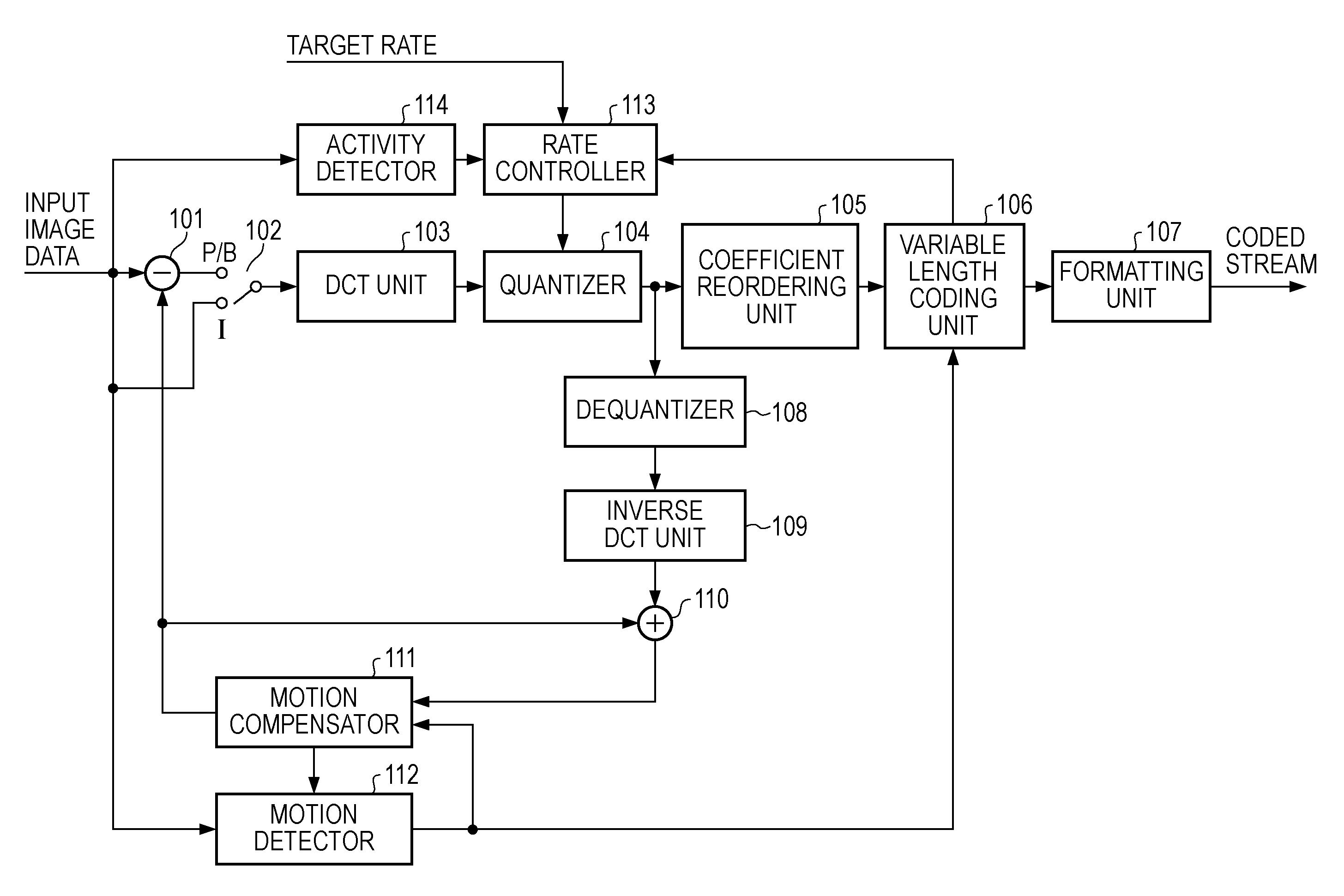
[0036]FIG. 1 illustrates a configuration of a coding apparatus according to at least one exemplary embodiment of the present invention. The coding apparatus of FIG. 1 is capable of coding input moving image signals according to the MPEG2 standard.

[0037]Referring to FIG. 1, moving image data supplied from a video camera, an input terminal, or the like is input frame-by-frame and supplied to a subtracter 101, a switch 102, a motion compensator 111, a motion detector 112, and an activity detector 114.

[0038]In the MPEG2 standard, a moving image signal is coded frame-by-frame by the combination of intraframe coding (I-pictures), interframe forward predictive coding (P-pictures), and interframe bidirectional predictive coding (B-pictures).

[0039]For coding I-pictures, the switch 102 is connected to an “I” side and allows an input image signal of one frame to be directly supplied to a DCT unit 103. The DCT unit 103 performs DCT processing on each DCT block of the input image signal, each DC...

second exemplary embodiment

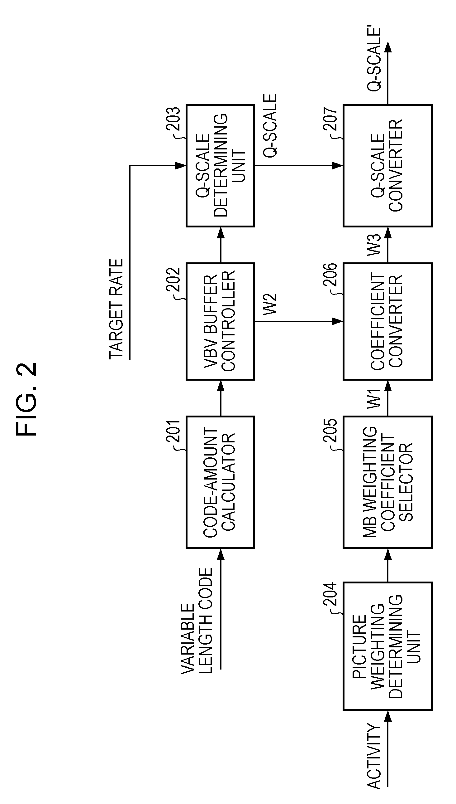
[0066]A second exemplary embodiment of the present invention will now be described. In the first exemplary embodiment described above, a weighting coefficient determined from the activity of an image is converted on the basis of the state of the VBV buffer. This can cause the value of W2 to be changed in the middle of one frame, and the improvement of image quality based on the use of activities may be less significant, particularly in MBs processed at a later stage in the processing of one screen.

[0067]Therefore, in the present exemplary embodiment, when the picture weighting determining unit 204 generates a weighting coefficient on the basis of an activity with respect to each MB, the activity to be supplied to the picture weighting determining unit 204 is converted according to the state of the VBV buffer.

[0068]FIG. 3 illustrates a configuration of a rate controller 113 according to the second exemplary embodiment. In FIG. 3, components similar to those of FIG. 2 are given the sa...

third exemplary embodiment

[0076]A third exemplary embodiment of the present invention will now be described. FIG. 6 illustrates a configuration of a rate controller 113 according to the third exemplary embodiment. In FIG. 6, components similar to those of FIG. 2 are given the same reference numerals.

[0077]Referring to FIG. 6, the Q-scale determining unit 203 determines a Q-scale in a similar manner to those of the foregoing exemplary embodiments and outputs the determined Q-scale to a switch 602.

[0078]On the other hand, the Q-scale converter 207 performs an operation using a weighting coefficient W1 for each MB output from the MB weighting-coefficient selector 205 and a Q-scale value from the Q-scale determining unit 203 in a similar manner to that described above, and outputs the resulting Q-scale′ to the switch 602.

[0079]Then, according to an instruction from a VBV buffer controller 601, the switch 602 selects either one of the Q-scale from the Q-scale determining unit 203 and the Q-scale′ from the Q-scale...


PUM


Abstract

An image processing apparatus includes a quantizing unit configured to quantize an input moving image signal using a set quantization scale; a coding unit configured to perform variable length coding on an output of the quantizing unit; an activity detecting unit configured to detect an activity of the input moving image signal; a quantization-scale determining unit configured to determine the quantization scale; a changing unit configured to change a value determined by the quantization-scale determining unit, and to set the changed value, as the quantization scale; and a filling level detecting unit configured to detect the filling level of a virtual buffer in a decoder which decodes the coded moving image signal, and to control the changing unit such that the degree of change in the quantization scale caused by use of the activity is reduced as the detected filling level decreases.

Description

BACKGROUND OF THE INVENTION[0001]1. Field of the Invention[0002]The present invention relates to image processing apparatuses and particularly to coding of image signals.[0003]2. Description of the Related Art[0004]The Moving Picture Experts Group (MPEG) standard and the H.264 (or MPEG4-advanced video coding (AVC)) standard are known as technical standards for coding image signals. These coding standards use techniques, such as discrete cosine transform (DCT), quantization, and variable length coding, and combine intraframe coding and interframe predictive coding to achieve coding of moving image signals.[0005]Also, for example, the MPEG2 standard defines a video buffer verifier (VBV) buffer model (i.e., virtual buffer model) to ensure real-time processing during decoding. In the VBV buffer model, the amount of data in a buffer memory during decoding must be maintained at a level between the upper limit of the VBV buffer size and zero byte. For example, at main profile at main level...

Claims


Application Information

Patent Timeline
Patent Type & Authority Applications(United States)
IPC IPC(8): G06K9/36H04N19/105H04N19/126H04N19/00H04N19/14H04N19/152H04N19/176H04N19/196H04N19/503H04N19/51H04N19/577H04N19/61H04N19/625H04N19/91
CPCH04N19/176H04N19/115H04N19/152H04N19/126H04N19/14H04N19/124
Inventor ANDO, TSUTOMU
Owner CANON KK
Learn More