Image forming apparatus having contactless type temperature sensor
a temperature sensor and image forming technology, applied in the field of image forming apparatus, can solve the problems of contactless type sensor, affecting the cost of consumables, and liable to appear as gloss, so as to improve the temperature detecting precision of temperature detecting sensor
- Summary
- Abstract
- Description
- Claims
- Application Information
AI Technical Summary
Benefits of technology
Problems solved by technology
Method used
Image
Examples
first embodiment
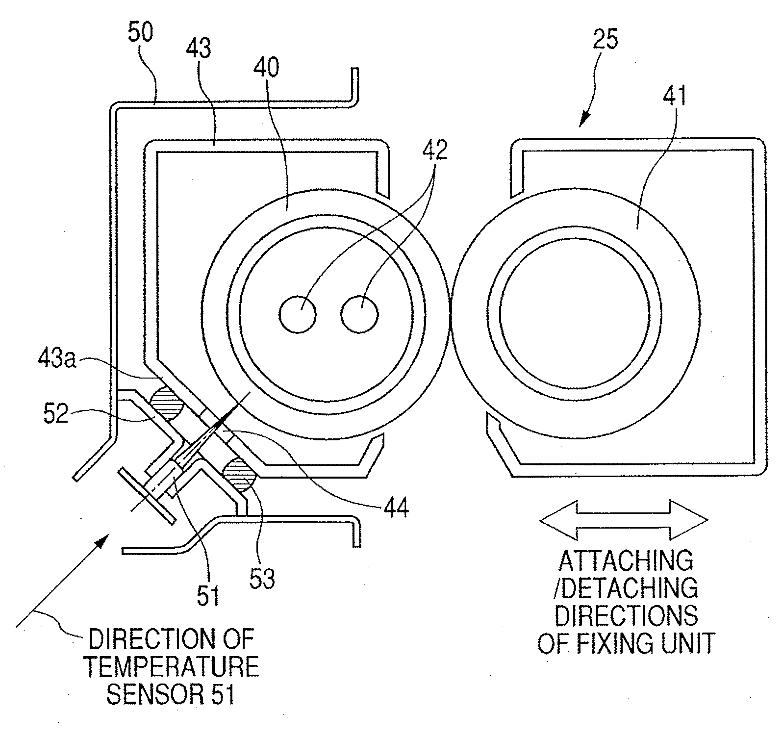
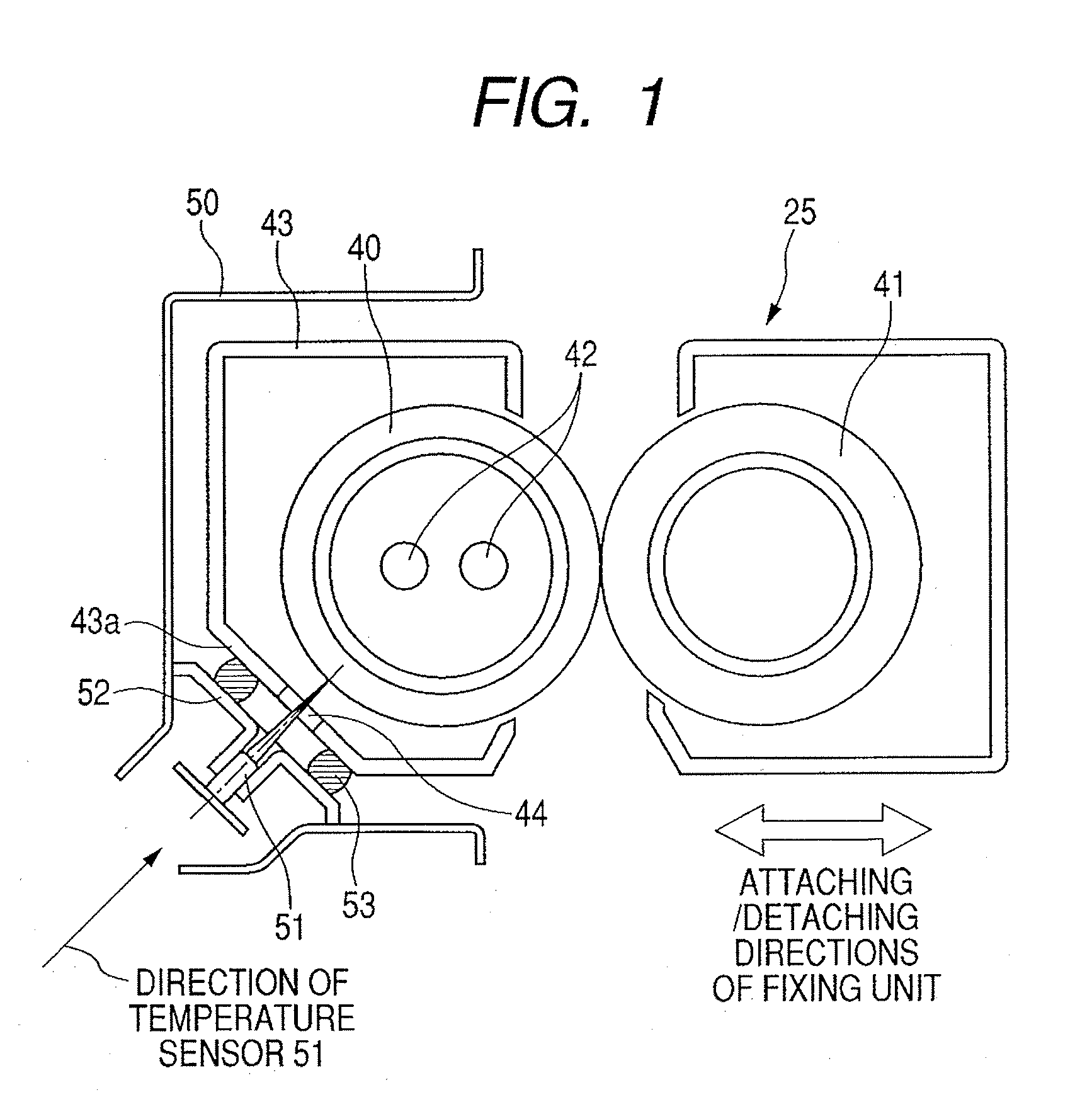
[0029]A first embodiment of the invention will be described with reference to FIGS. 1 and 4. FIG. 1 is a schematic cross sectional view of a fixing unit and its peripheral component elements in an image forming apparatus of the first embodiment of the invention. FIG. 4 is a schematic cross sectional view of the image forming apparatus (hereinafter, referred to as a printer) to which the invention is applied.
[0030]FIG. 4 illustrates a printer main body 1. An engine portion to form primary images of four colors in total of yellow, magenta, cyan, and black is arranged in an upper portion of the printer main body 1.
[0031]Print data transmitted from an external apparatus such as a personal computer is received by a controller for controlling the printer main body 1 and output as writing image data to a laser scanner 10 of each color. The laser scanner emits a laser beam onto a photosensitive drum 12 and draws a light image according to the writing image data.
[0032]The engine portion has ...
second embodiment
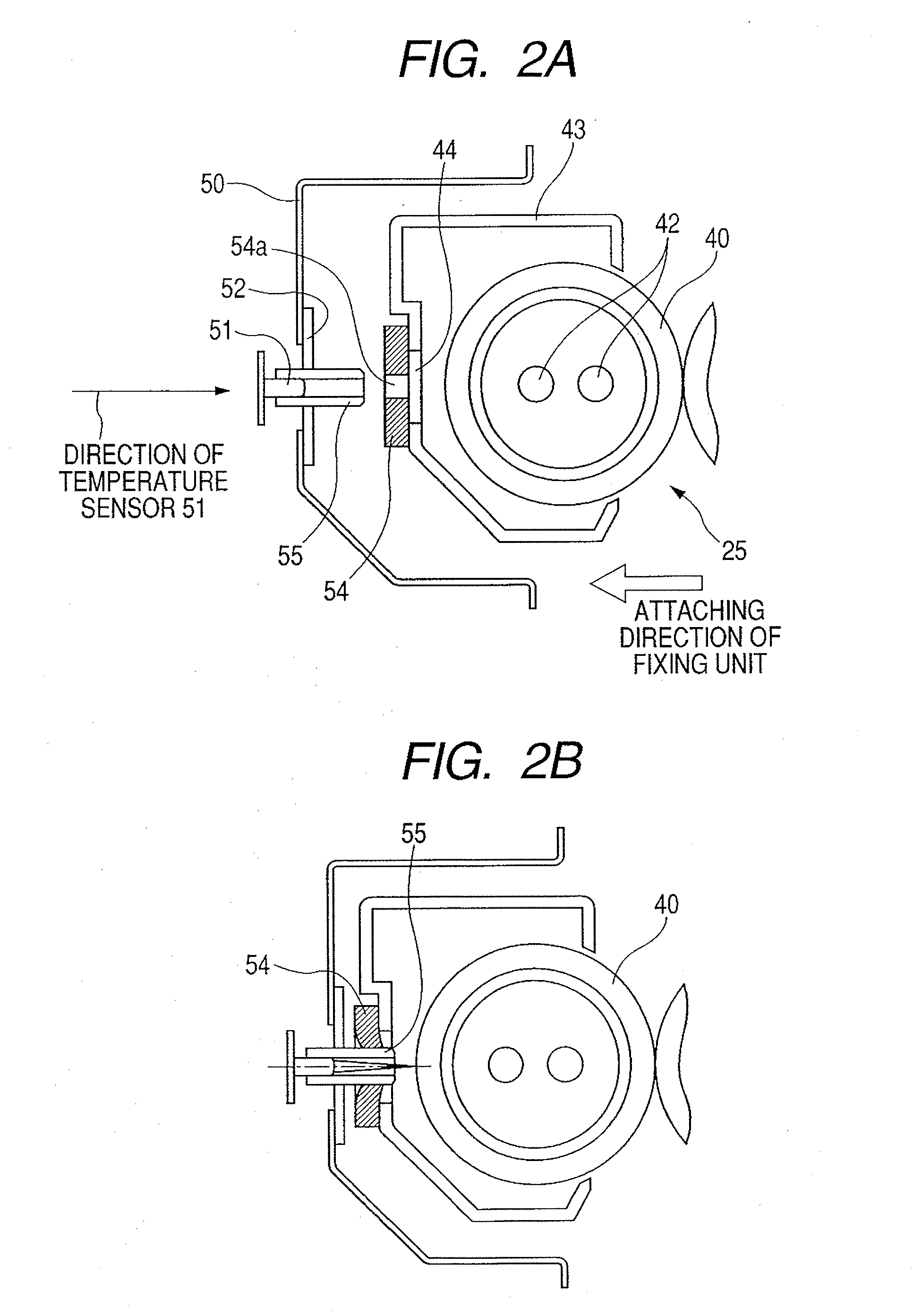
[0055]FIGS. 2A and 2B are diagrams illustrating the second embodiment. FIG. 2A illustrates a state before the fixing unit 25 is attached to the printer main body 1. FIG. 2B illustrates a state where the fixing unit 25 has been attached. In FIGS. 2A and 2B, component elements similar to those in FIG. 1 are designated by the same reference numerals and their description is omitted.
[0056]In the embodiment illustrated in FIGS. 2A and 2B, a sealing member 54 as a sealing unit is provided on the cover member 43 of the fixing unit 25. The virtual line (that is, the direction of the temperature sensor 51) connecting the temperature sensor 51 and the center of the opening portion 44 of the fixing unit in the state where the fixing unit 25 has been attached to the apparatus main body 1 is almost parallel with the direction in which the fixing unit 25 is attached to the apparatus main body 1.
[0057]In the sealing member 54, a hole portion 54a smaller than the opening portion 44 is formed near t...
third embodiment
[0060]Although the example in which the raw material itself of the sealing member can be compressed and deformed (elastic deformation) has been described in the first and second embodiments, an effect similar to that in the first embodiment can be also obtained by another construction. A third embodiment of the invention will now be described with reference to FIGS. 3A and 3B.
[0061]FIGS. 3A and 3B are schematic cross sectional views of the fixing unit 25 and its peripheral component elements according to the third embodiment of the invention. FIG. 3A illustrates a state before the fixing unit 25 is attached to the printer main body 1. FIG. 3B illustrates a state where the fixing unit 25 has been attached. A construction of the fixing unit 25 and a construction in which the contactless temperature sensor 51 has been fixed to the frame 50 of the printer main body 1 through the sensor holder 52 are similar to those in the first embodiment. Component elements similar to those in the fir...
PUM
 Abstract
Description
Claims
Application Information
 - R&D
- Intellectual Property
- Life Sciences
- Materials
- Tech Scout
- Unparalleled Data Quality
- Higher Quality Content
- 60% Fewer Hallucinations
Browse by: Latest US Patents, China's latest patents, Technical Efficacy Thesaurus, Application Domain, Technology Topic, Popular Technical Reports.
© 2025 PatSnap. All rights reserved.Legal|Privacy policy|Modern Slavery Act Transparency Statement|Sitemap|About US| Contact US: help@patsnap.com


