Microcircuits for small engines

Active Publication Date: 2007-08-02
RAYTHEON TECH CORP
View PDF14 Cites 28 Cited by
  • Summary
  • Abstract
  • Description
  • Claims
  • Application Information

AI Technical Summary

Benefits of technology

[0006] Further in accordance with the present invention, a method for designing a turbine engine component for use in a small engine application is provided. The method broadly comprises the steps of: designing an airfoil portion having a root portion,

Problems solved by technology

This is not possible to achieve.

Method used


Image

  • Microcircuits for small engines
  • Microcircuits for small engines
  • Microcircuits for small engines

Examples


Example

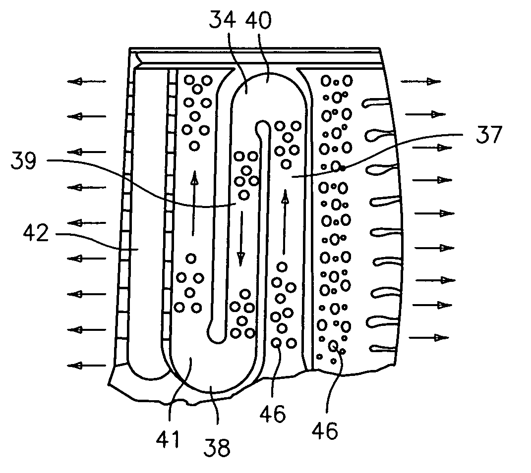
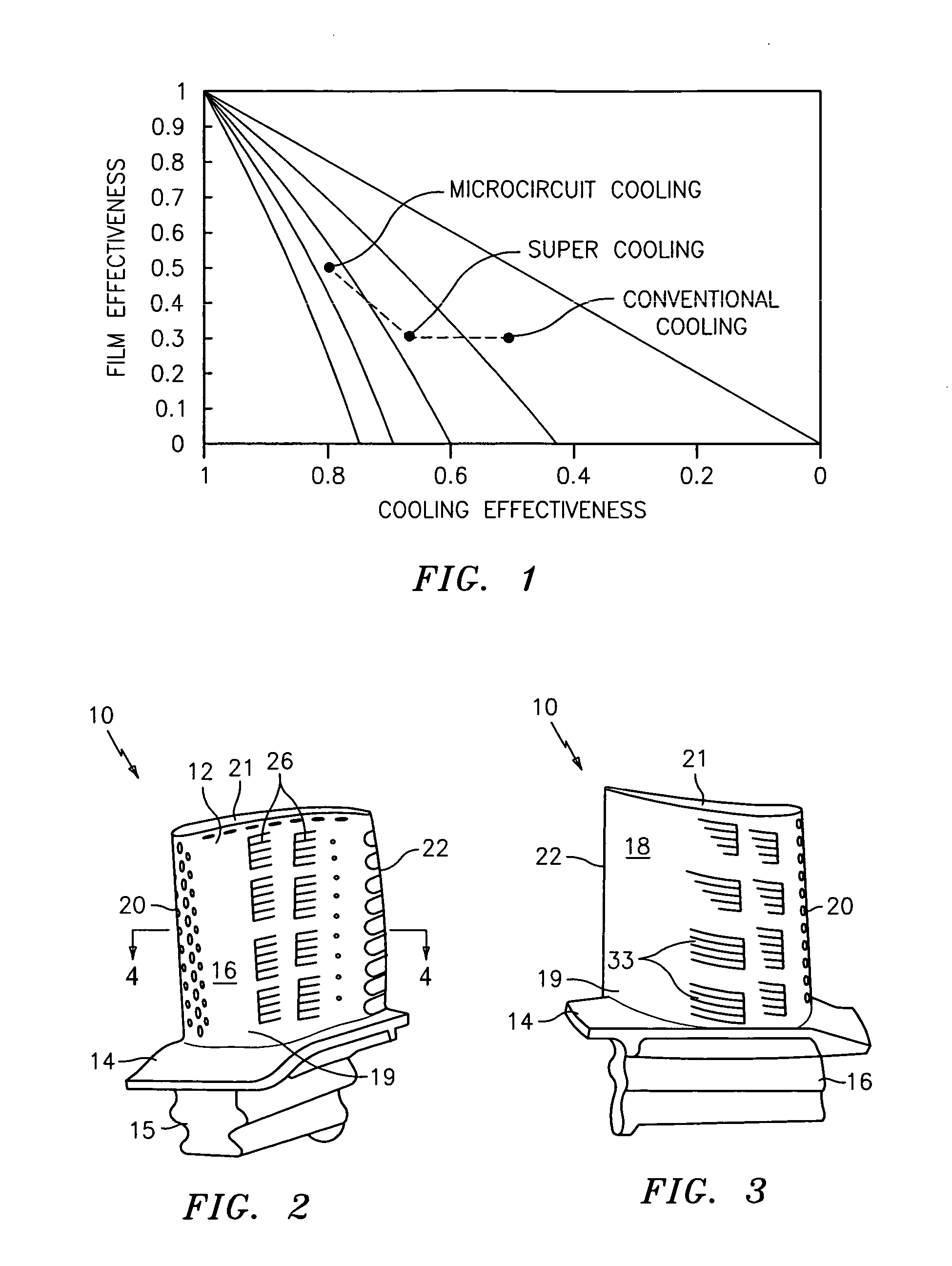
[0018] Referring now to FIGS. 2-5, there is illustrated a cooling scheme for cooling a turbine engine component 10, such as a turbine blade or vane, which can be used in a small engine application. As can be seen from FIGS. 2 and 3, the turbine engine component 10 has an airfoil portion 12, a platform 14, and an attachment portion 15. The airfoil portion 12 includes a pressure side 16, a suction side 18, a leading edge 20, a trailing edge 22, a root portion 19, and a tip portion 21.

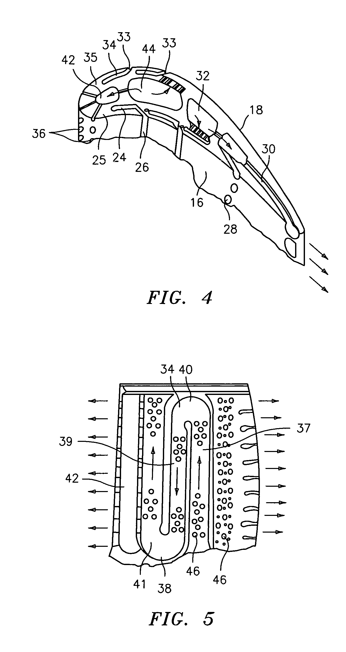
[0019]FIG. 4 is a sectional view of the airfoil portion 12. As shown therein, the pressure side 16 may include one or more cooling circuits or passages 24 with slot film cooling holes 26 for distributing cooling fluid over the pressure side 16 of the airfoil portion 12. The cooling circuit(s) or passage(s) 24 are embedded within the pressure side wall 25 and may be made using a refractory metal core (not shown), which refractory metal core may have one or more integrally formed tabs that form the cooling...


PUM


Abstract

A turbine engine component for use in a small engine application has an airfoil portion having a root portion, a tip portion, a suction side wall, and a pressure side wall. The suction side wall and the pressure side wall have the same thickness. Still further, the turbine engine component has a platform with an internal cooling circuit.

Description

BACKGROUND OF THE INVENTION [0001] (1) Field of the Invention [0002] The present invention relates to an improved design for a turbine engine component used in small engine applications and to a method for designing said turbine engine component. [0003] (2) Prior Art [0004] There are existing cooling schemes currently in operation for small engine applications. Even though the cooling technology for these designs has been very successful in the past, it has reached its culminating point in terms of durability. That is, to achieve superior cooling effectiveness, these designs have included many enhancing cooling features, such as turbulating trip strips, shaped film holes, pedestals, leading edge impingement before film, and double impingement trailing edges. For these designs, the overall cooling effectiveness can be plotted in durability maps as shown in FIG. 1, where the abscissa is the overall cooling effectiveness parameter and the ordinate is the film effectiveness parameter. T...

Claims


Application Information

Patent Timeline
IPC IPC(8): F01D5/18
CPCB22C9/04B22C9/10F01D5/187F05D2240/81F05D2230/211F05D2260/202F05D2250/185F01D5/14F01D5/26F01D5/18
Inventor CUNHA, FRANKABDEL-MESSEH, WILLIAM
Owner RAYTHEON TECH CORP
Why Eureka
Try Eureka