Integral sensor and control for dry run and flow fault protection of a pump

a sensor and control technology, applied in the field of pumps, can solve the problems of increasing the work required for installation, increasing the risk of leakage in the plumbing, and adding to the physical component coun

Inactive Publication Date: 2007-08-02
ITT MFG ENTERPRISES LLC
View PDF19 Cites 49 Cited by
  • Summary
  • Abstract
  • Description
  • Claims
  • Application Information

AI Technical Summary

Benefits of technology

[0010] In operation, the invention uses a microcontroller (MCU), and one or more computer programs, a pressure sensor integral to the pump, and electrical or electronic power switching components. As such, the invention does not require components external to the pump, nor does it require intrusions into the inlet or outlet plumbing lines, thus avoiding the risk of damage to the plumbing caused by inserting the pressure sensor into the plumbing line, and thus also avoiding the associated burdens of parts and installation.
[0012] As is known, unusually large fluid flows in a plumbing system may result from failure or damage to the plumbing system. Such “flow faults” (analogous to excessively large electrical current flow in an “electrical fault”) can cause the pressure of the fluid in the system served by the pump to fall to a low value. The pump controller can be configured (via the computer programs or ASICs) to disregard flow fault pressures, or to act on them in a protective response in conjunction with any of various decision approaches. Thus, the invention not only can protect against dry run conditions (where there is no fluid remaining to be supplied to the fluid system), but also against undesired, unusually large flow conditions, i.e. flow faults.

Problems solved by technology

This creates a risk of leaks in the plumbing, increases the work required for installation, and adds to the physical component count.
In addition, such pump control devices typically lack input and decision-making flexibility in that they are designed to respond to a single-variable input stimulus (pressure), and they typically lack variable output functionality since they can only switch the pump to an ON or OFF state.
This can be problematic if conditions on the sensed side of the pump are within acceptable operating limits, but conditions on the other side are not.
For example, if a pump control device is configured only to respond to vacuum conditions appearing on the supply side of a pump, then no protection is afforded against uncontrolled flows resulting from catastrophic failure of, or damage to, the plumbing system charged by the pump.
As is known, unusually large fluid flows in a plumbing system may result from failure or damage to the plumbing system.
Such “flow faults” (analogous to excessively large electrical current flow in an “electrical fault”) can cause the pressure of the fluid in the system served by the pump to fall to a low value.

Method used


Image

  • Integral sensor and control for dry run and flow fault protection of a pump
  • Integral sensor and control for dry run and flow fault protection of a pump
  • Integral sensor and control for dry run and flow fault protection of a pump

Examples


Embodiment Construction

FIG. 1

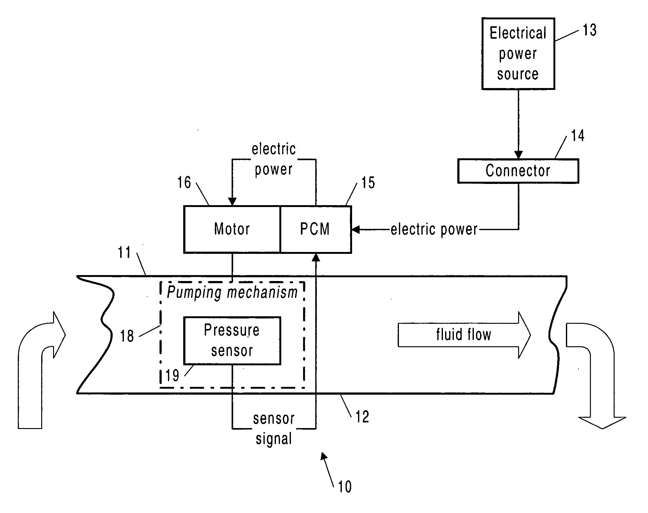
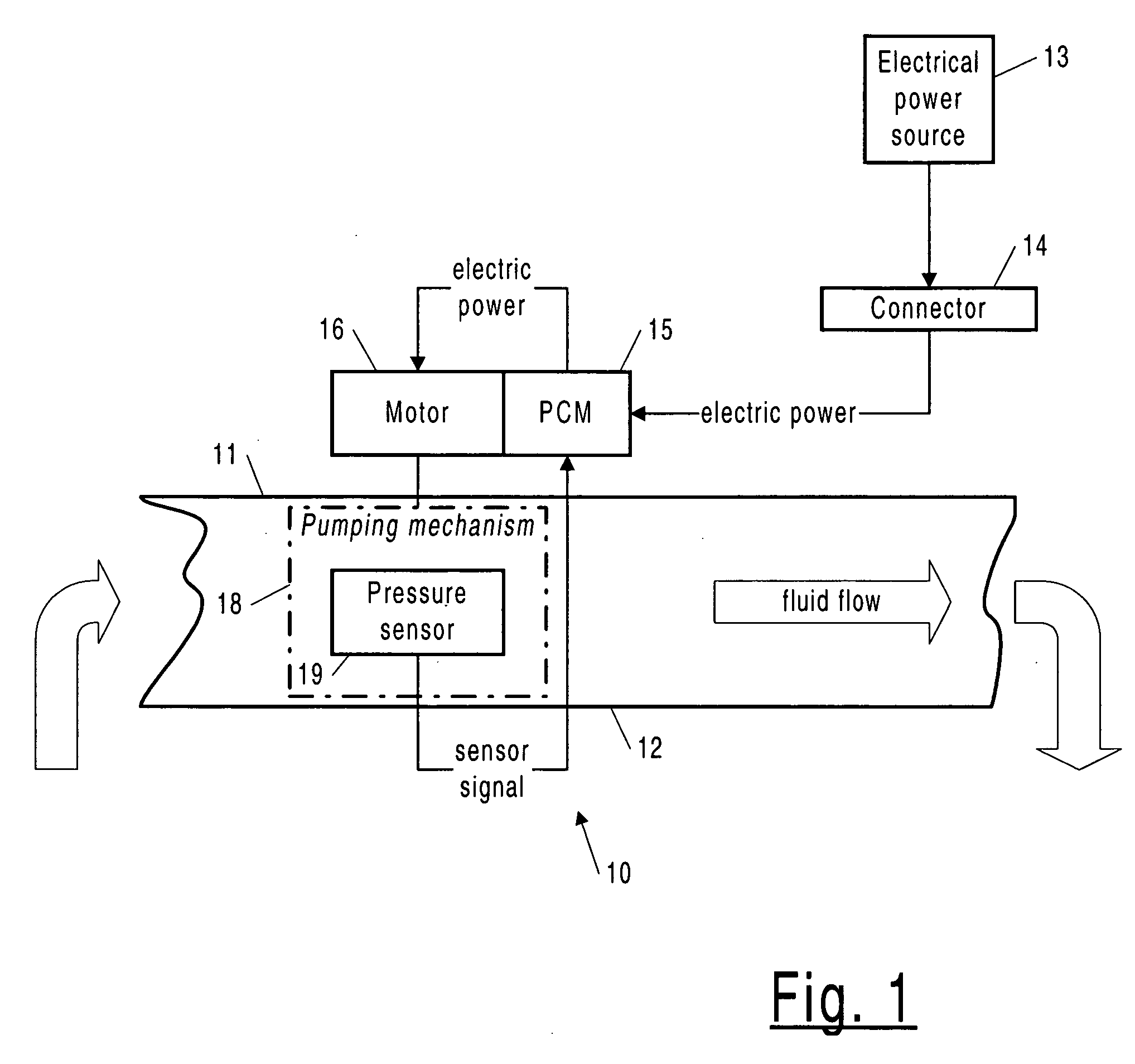
[0017]FIG. 1 shows a pump system 10 according to the invention, for pumping a fluid. It includes a pump control module (PCM) 15 serving as a controller for a pump electric motor 16, built into or attached to the pump. An electrical power source 13 (AC or DC), is connected to the PCM 15 by an electrical connection 14.

[0018] The pump system includes a pumping mechanism 18 driven by the pump motor 16 and installed in a plumbing line, so as to have inlet plumbing 11 and outlet plumbing 12. The pumping mechanism includes an inlet cavity and an outlet cavity, and a structure (not shown) such as valve chambers in a positive displacement diaphragm pump, located between the two cavities and driven by the electric motor in a cyclical pattern so as to give rise to a pumping action. A pressure sensor 19 is built into the inlet and / or outlet cavity, and communicatively coupled to the PCM so as to provide to the PCM signals indicative of the fluid pressure in the (inlet or outlet) cavity. ...


PUM


Abstract

A pump providing fault protection based on a controller receiving sensed pressure values from a pressure sensor included in a cavity of the pump, so as to be integral with the pump.

Description

CROSS REFERENCE TO RELATED APPLICATION [0001] Reference is made to and priority claimed from U.S. provisional application Ser. No. 60 / 701,607 filed Jul. 21, 2005.FIELD OF THE INVENTION [0002] The present invention relates to a pump, and more particularly to a controller or device built into a pump for providing protection for the pump against dry run and flow fault conditions. BACKGROUND OF THE INVENTION [0003] Existing pump control devices for providing protection for a smaller-sized water pump against dry run and flow fault conditions typically include a pressure-activated electrical switch that turns off power to the pump when the monitored pressure is too low (or is a vacuum). The pressure-activated switch is installed externally to the pump, in such a way as to monitor the inlet and / or outlet pressure. The control is reflexive, in that a drop in pressure below the threshold of the pressure-activated switch will cause the switch to operate. The pressure-activated switch is typic...

Claims


Application Information

Patent Timeline
Patent Type & Authority Applications(United States)
IPC IPC(8): F04B49/06
CPCF04B43/0081F04B49/022F04B2205/04F04B49/10F04B2205/02F04B49/06
Inventor WALLS, JAMES C.CAIN, JEFFFONG, JOHN
Owner ITT MFG ENTERPRISES LLC
Why Eureka
Try Eureka