Oil separation structure in compressor

Inactive Publication Date: 2007-08-02
TOYOTA IND CORP
View PDF6 Cites 1 Cited by
  • Summary
  • Abstract
  • Description
  • Claims
  • Application Information

AI Technical Summary

Benefits of technology

[0004] Accordingly, it is an objective of the present invention to provide an oil separation structure that is

Problems solved by technology

However, if the swirl chamber (oil separation chamber) is excessively prolonged in the direction along the cylindrical oil separator,

Method used


Image

  • Oil separation structure in compressor
  • Oil separation structure in compressor
  • Oil separation structure in compressor

Examples


Embodiment Construction

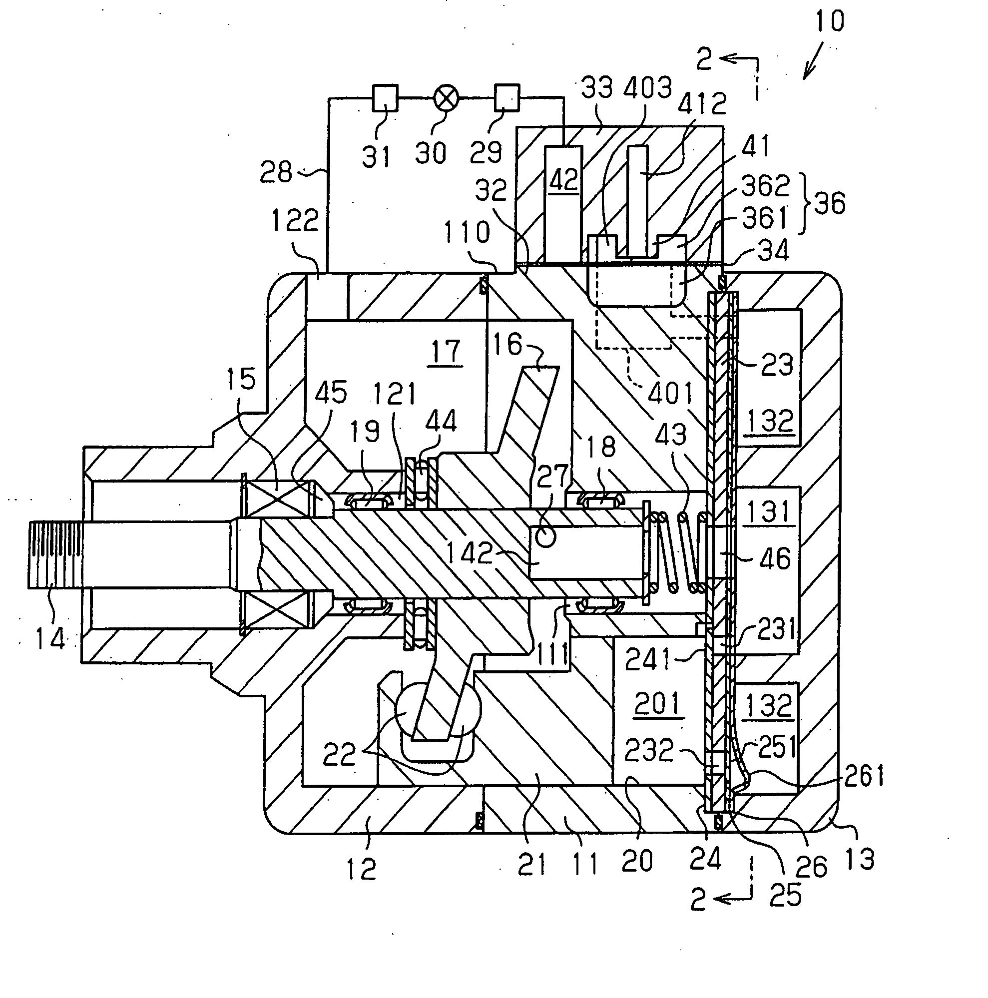
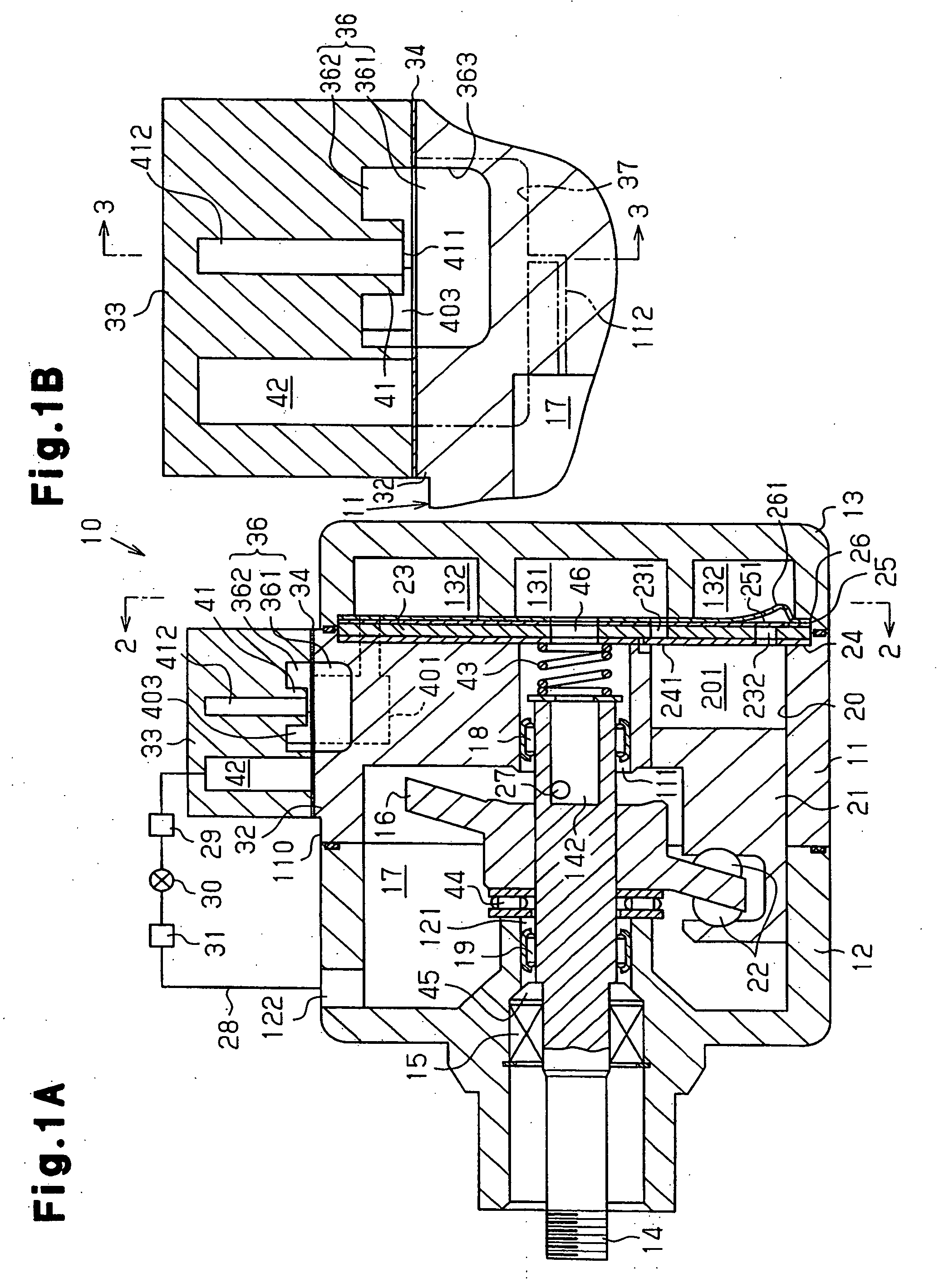
[0015] A fixed displacement piston compressor according to a first embodiment of the present invention will now be described with reference to FIGS. 1A to 5.

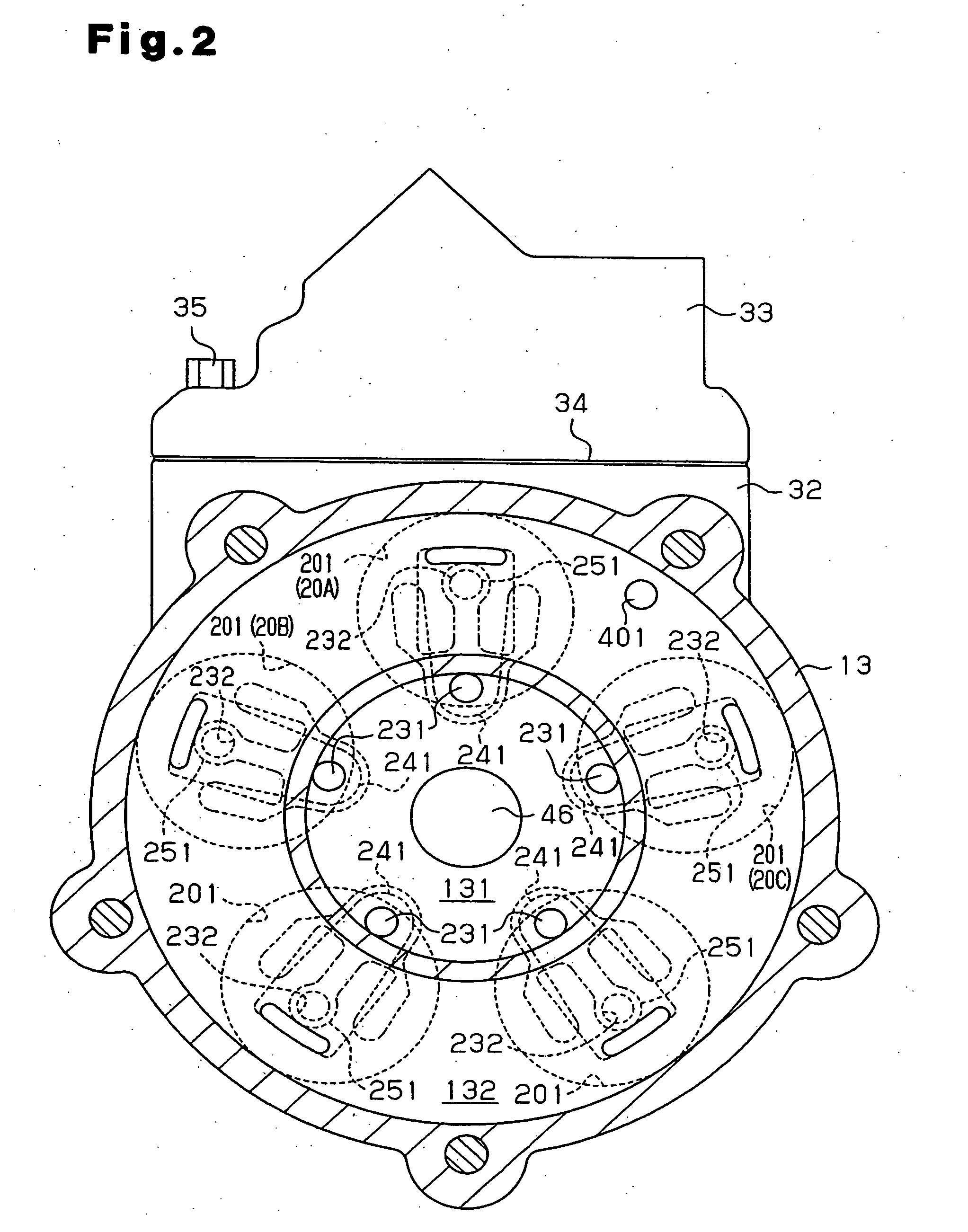
[0016] As shown in FIG. 1A, a front housing member 12 and a rear housing member 13 are coupled to a cylinder block 11. A suction chamber 131 and a discharge chamber 132 are defined in the rear housing member 13. The cylinder block 11, the front housing member 12, and the rear housing member 13 form a housing of a compressor 10.

[0017] A rotary shaft 14 is rotatably supported by the cylinder block 11 and the front housing member 12. The rotary shaft 14 extends through shaft holes 111, 121 formed in the cylinder block 11 and the front housing member 12. The rotary shaft 14 is supported by the cylinder block 11 and the front housing member 12 with radial bearings 18, 19 located in the shaft holes 111, 121.

[0018] A swash plate 16 is fixed to the rotary shaft 14. The swash plate 16, which functions as a cam member, is accommodated ...


PUM


Abstract

A muffler forming member defines a muffler chamber. Refrigerant discharged from a cylinder bore is sent to the muffler chamber. The muffler forming member is coupled to a circumferential surface of a housing of a compressor. An oil separation chamber is defined in a discharge pressure zone of the compressor. The oil separation chamber separates the oil from the refrigerant discharged from the cylinder bore. The oil separation chamber extends into both the muffler forming member and the housing. The oil separation chamber has a refrigerant inlet through which the refrigerant flows into the oil separation chamber. The refrigerant inlet is formed in the muffler forming member. Therefore, the oil separation chamber is prolonged in the direction from the muffler forming member toward the housing, thereby improving the oil separation performance.

Description

BACKGROUND OF THE INVENTION [0001] The present invention relates to an oil separation structure in a compressor. [0002] Japanese Laid-Open Patent Publication No. 11-182430 discloses a compressor having a muffler forming portion. The muffler forming portion is located on the outer circumference of a cylinder block that forms a part of the compressor housing. A first muffler chamber is defined in the muffler forming portion. The muffler forming portion is coupled to a muffler cover (muffler forming member). A second muffler chamber is defined in the muffler cover. A swirl chamber is defined in the first muffler chamber. A downwardly projecting cylindrical oil separator is provided in the swirl chamber. As pistons reciprocate, refrigerant is discharged to a discharge chamber from the cylinder bores. The refrigerant is then led to the first muffler chamber via a discharge passage. After entering the first muffler chamber, the refrigerant flows into the swirl chamber. The refrigerant flo...

Claims


Application Information

Patent Timeline
IPC IPC(8): F04B39/00
CPCF04B27/109F04B39/0061F04B39/16F04B39/04F04B39/0072F04B27/1081F05B2210/12F05B2210/14F05B2260/962F25B43/02Y10S417/00
Inventor INOUE, YOSHINORIKOEDA, NAOKISAKAMOTO, MASAYATARUTANI, TOMOJI
Owner TOYOTA IND CORP
Why Eureka
Try Eureka