Exhaust treatment device with sensor and method of making

a technology of exhaust gas sensor and treatment device, which is applied in the direction of exhaust treatment, combination devices, mechanical devices, etc., can solve the problems of limiting the positioning and configuration of the gas sensor within the exhaust system, requiring a sufficient amount of free space between the bricks, and not being optimal mounting locations for the exhaust sensor, etc., to achieve the effect of substantial cost, performance, reliability and manufacturing advantages

Active Publication Date: 2007-08-02
KATCON GLOBAL
View PDF8 Cites 27 Cited by
  • Summary
  • Abstract
  • Description
  • Claims
  • Application Information

AI Technical Summary

Benefits of technology

[0006]Exemplary embodiments of the present invention relate to the incorporation of a mid-bed oxygen sensor into an internally insulated catalytic converter or exhaust treatment device with butted catalyst bricks or a single brick with one or more washcoatings. Exemplary embodiments of the present invention are directed to a single or butted brick arrangement, wherein a single brick arrangement will have a receiving area for a portion of the gas sensor disposed in it and if two bricks are used, the ends of the two bricks will be butted to each other and a receiving area for a portion of the gas sensor is disposed in at least one of the catalyst bricks butted against each other. This single or butted brick arrangement offers substantial cost, performance, reliability, and manufacturing advantages over using non-butted (spaced) pair of catalyst bricks.

Problems solved by technology

Furthermore and due to application requirements, the exhaust system itself will have unique exterior configurations, which may not be optimal mounting locations for exhaust sensors (e.g., irregular welding surfaces).
Accordingly, exhaust system designs limit the positioning and configuration of the gas sensor within the exhaust system.
However, this requires a sufficient amount of free space between the bricks for the sensing element of the gas sensor to be mounted within the flow path of and between the catalyst bricks (e.g., mid-stream mounting).

Method used


Image

  • Exhaust treatment device with sensor and method of making
  • Exhaust treatment device with sensor and method of making
  • Exhaust treatment device with sensor and method of making

Examples


Embodiment Construction

[0020]Reference is made to U.S. patent application Ser. No. 09 / 903,983, filed Jul. 12, 2001, the contents of which are incorporated herein by reference thereto.

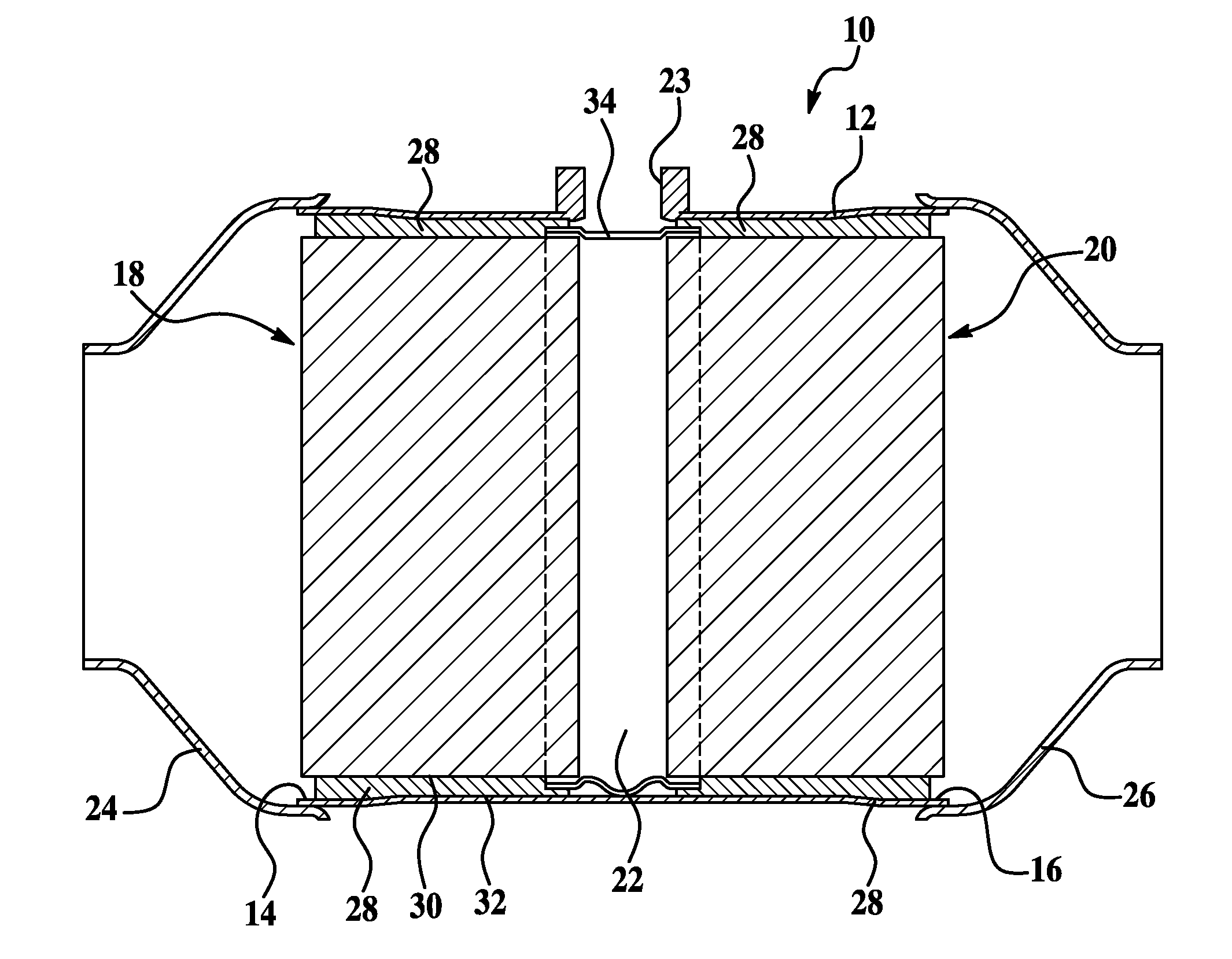
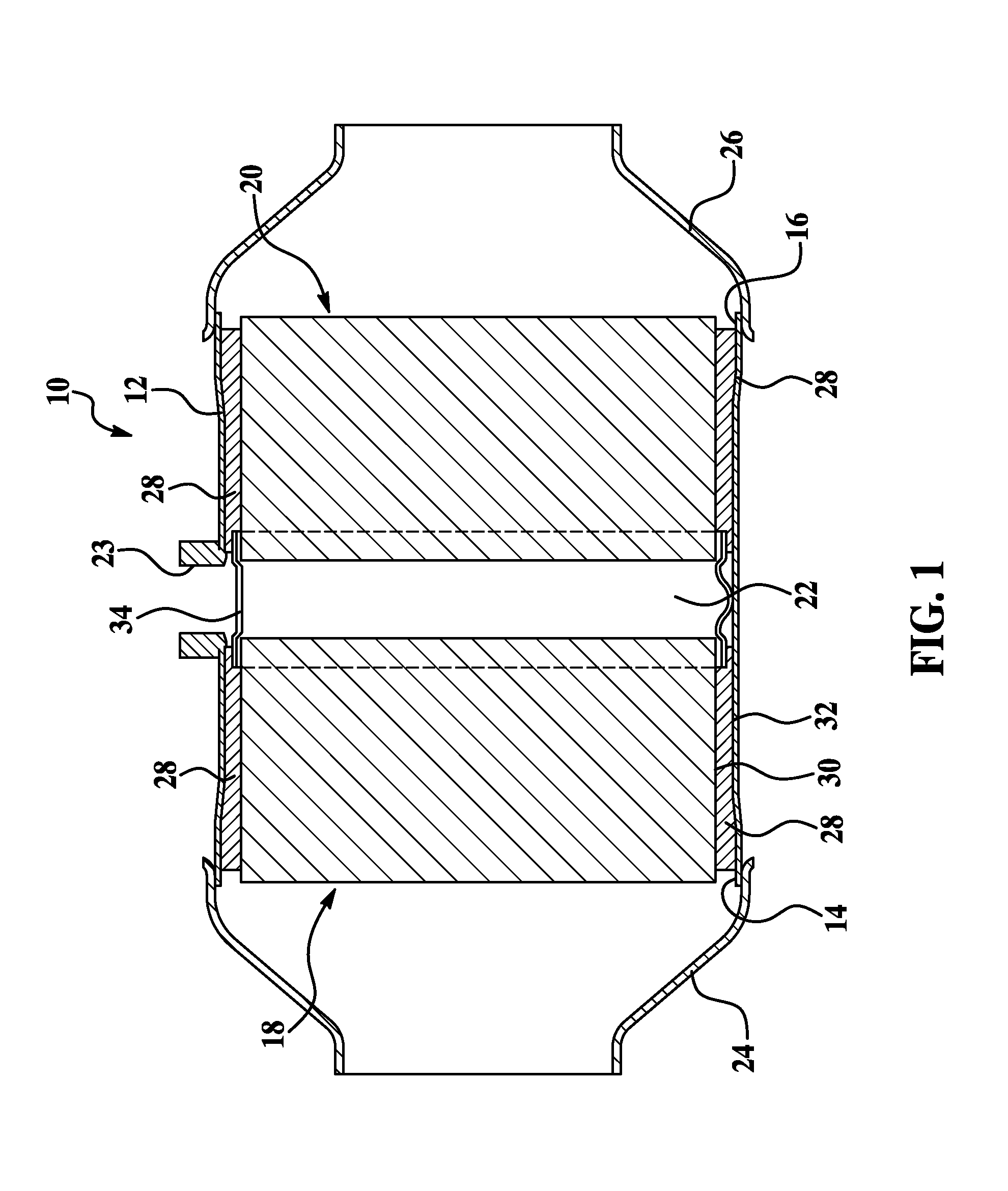
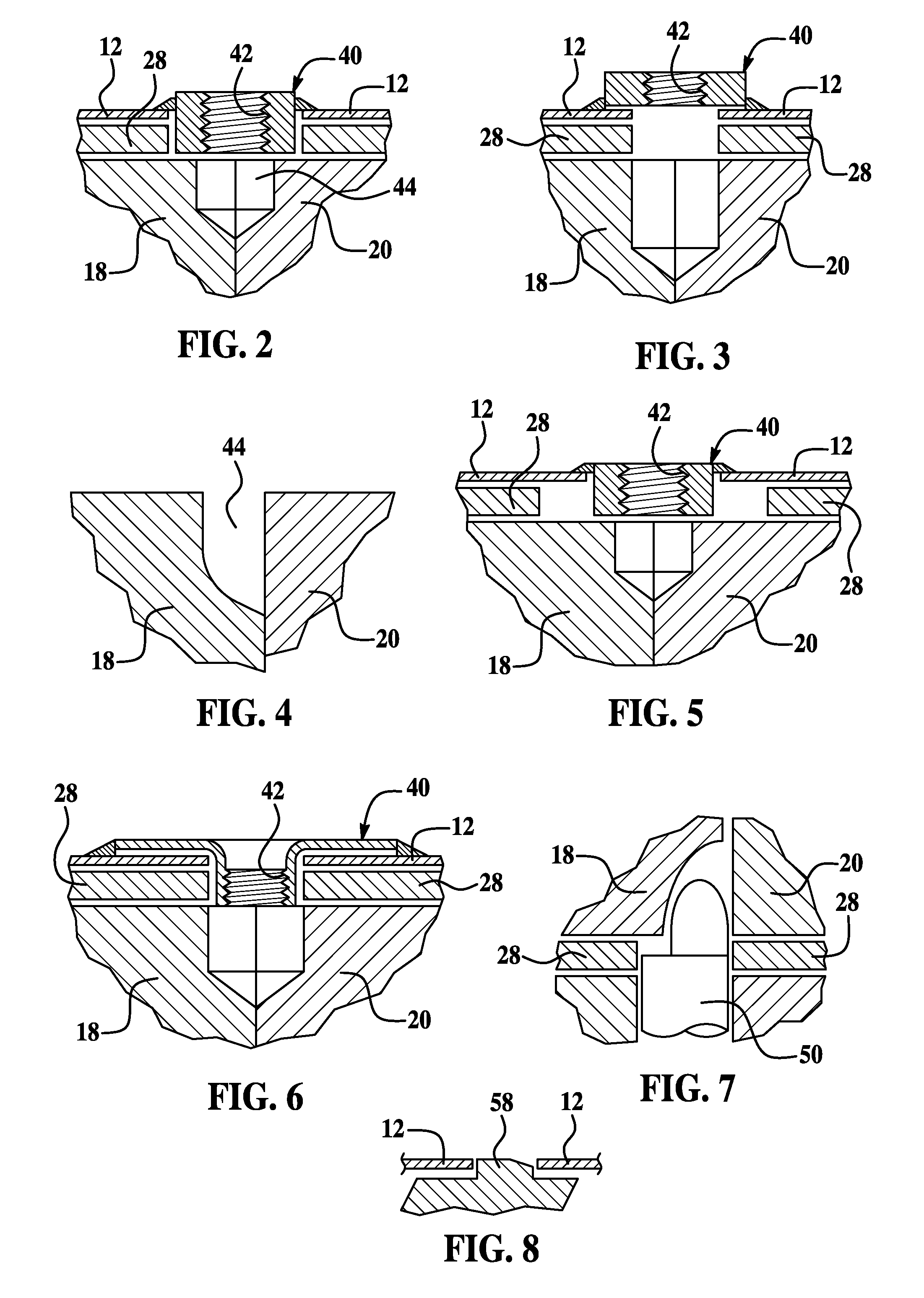
[0021]Exemplary embodiments of the present invention relate to an exhaust system comprising a gas sensor mounting boss integrally formed in a shell portion of a catalytic converter of the exhaust system, wherein the gas sensor mounting boss is formed in a location that corresponds to an area disposed within a portion of at least one of the catalyst bricks disposed within the shell or housing of the catalytic converter. In accordance with an exemplary embodiment, the gas sensor can be any conventional sensor such as oxygen sensors currently used in vehicle exhaust systems.

[0022]Exemplary embodiments of the present invention relate to the incorporation of a mid-bed oxygen sensor or any other type of sensor into an internally insulated catalytic converter or exhaust treatment device with single or butted catalyst bricks. Exempla...


PUM

PropertyMeasurementUnit
temperaturesaaaaaaaaaa
areaaaaaaaaaaa
gas compositionaaaaaaaaaa

Abstract

An exhaust treatment device, comprising: a shell portion defining an inlet opening and an outlet opening; at least one catalyst brick being inserted within the shell portion; an insulative material disposed between the shell portion and the at least one catalyst brick; and a sensor receiving area formed in at least one catalyst brick.

Description

CROSS REFERENCE TO RELATED APPLICATIONS:[0001]This application claims the benefit of U.S. Provisional Patent Application Ser. No. 60 / 764,304, filed Feb. 1, 2006, the contents of which are incorporated herein by reference thereto.BACKGROUND[0002]The present invention relates to exhaust treatment devices. More particularly, the present invention relates to an exhaust treatment device with an exhaust gas sensor.[0003]Oxygen gas sensors or exhaust gas sensors have been used in vehicles to sense the presence of constituents (e.g., oxygen, hydrocarbons, nitrous oxides, etc.) in an exhaust gas flow and to sense and / or signal, for example, when an internal combustion engine switches from rich to lean or lean to rich operation or when a catalyst of the exhaust treatment device is no longer operating within a desired range.[0004]Because exhaust gas sensors are required to be positioned within an exhaust gas flow, the exhaust gas sensor is usually mounted to a portion of the exhaust system. Fu...

Claims


Application Information

Patent Timeline
Patent Type & Authority Applications(United States)
IPC IPC(8): B01D50/00B01D53/34
CPCB01D53/9454B01D53/9477F01N11/00F01N13/017Y02T10/47Y02T10/22F01N13/008Y02T10/12Y02T10/40
Inventor ROTH, GREGORY T.OWEZARCH, EDWARD A.SARSFIELD, ROBERT A.
Owner KATCON GLOBAL
Why Eureka
Try Eureka