
Apparatus and method for manufacturing flat display panel

Inactive Publication Date: 2007-08-02
LG ELECTRONICS INC
View PDF8 Cites 1 Cited by
  • Summary
  • Abstract
  • Description
  • Claims
  • Application Information

AI Technical Summary

Benefits of technology

[0013]Accordingly, the present invention has been made to solve the above-mentioned problems occurring in the prior art, and it is an object of the present invention to form an electrode through a simple procedure.
[0015]It is still another object of the present invention to accurately define a relative position of electrodes formed on a substrate of a flat display panel.

Problems solved by technology

The conventional plasma display panel constructed and manufactured as mentioned above has problems as described below.
Therefore, as the procedure for forming the electrode 3 requires a lengthy period, productivity is deteriorated.

Method used


Image

  • Apparatus and method for manufacturing flat display panel
  • Apparatus and method for manufacturing flat display panel
  • Apparatus and method for manufacturing flat display panel

Examples


Embodiment Construction

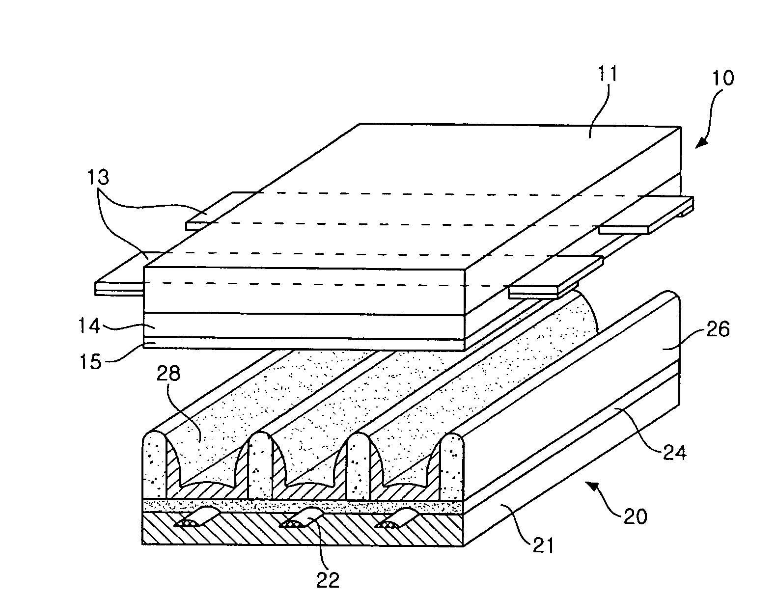
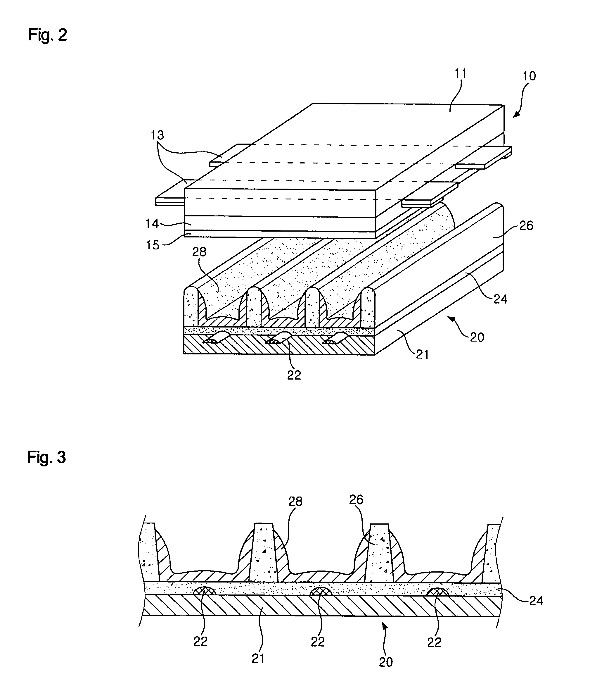
[0038]Hereinafter, specific embodiments of a flat display panel and a method for manufacturing the same in accordance with the present invention will be described in detail with reference to FIGS. 2 through 5. For the sake of convenience in explanation, FIG. 2 shows the construction of a three electrode face-discharge type plasma display panel.

[0039]In the present invention, a front panel 10 and a rear panel 20 are coupled with each other under a vacuum condition to constitute a plasma display panel. In the front panel 10, a plurality of sustain electrodes 13 for sustain discharge, a dielectric layer 14 for limiting a discharge current, and a protective layer 15 for protecting the dielectric layer 14 are sequentially formed on a first substrate 11.

[0040]A second substrate 21 for forming the skeleton of the rear panel 20 has the shape of a plate having a predetermined area. A plurality of address electrodes 22 is formed on the second panel 21 to elongate in one direction. The address...


PUM


Abstract

Disclosed are an apparatus and method for manufacturing a flat display panel. In forming sustain electrodes and address electrodes, to which electricity is supplied to discharge, on front and rear panels, electrode material, which resides in electrode forming grooves formed on the surface of an electrode roll and each having the same shape as that of electrodes, is transferred on a substrate. The electrode roll transfers the electrode material to the substrate while coming into close contact with and rotating on the substrate. The electrode material adhering to the surface of the electrode roll using a cleaner before the electrode roll transfers the electrode material to the substrate.

Description

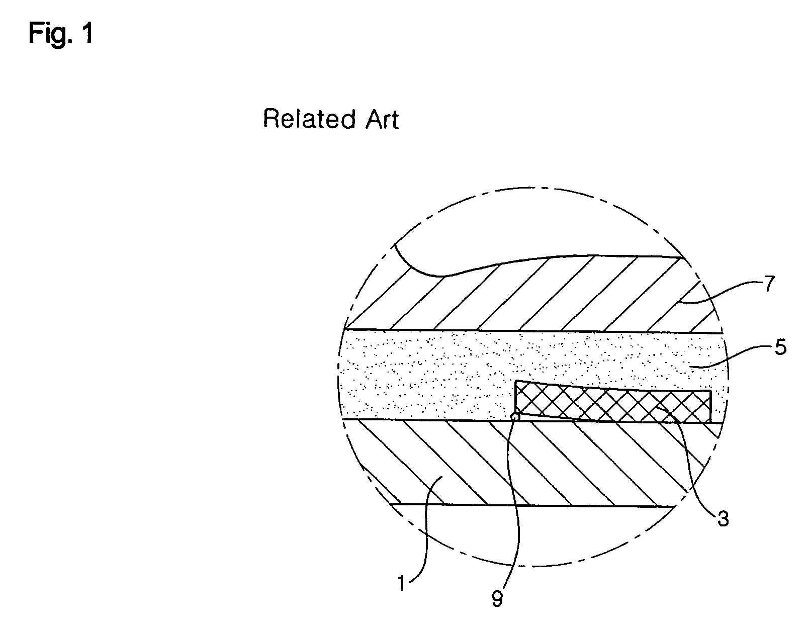
BACKGROUND OF THE INVENTION[0001]1. Field of the Invention[0002]The present invention relates to a flat display panel, and more particularly to an apparatus and method for manufacturing a flat display panel in which a front flat panel and a rear panel are coupled with each other to display an image.[0003]2. Description of the Prior Art[0004]As is generally known in the art, flat display panels include a liquid crystal display panel and a plasma display panel. Between these display panels, the plasma display panel is a kind of image display device in which front and rear panels made from glass substrate are air-tightly coupled with each other to display an image using an electric discharge phenomenon of a gas in the space defined between the front and rear panels.[0005]FIG. 1 illustrates the construction of the main part of a conventional plasma display panel. The drawing exemplifies the rear panel of the plasma display panel. Referring to FIG. 1, an electrode 3 is formed on a substr...

Claims


Application Information

Patent Timeline
IPC IPC(8): H01L21/336
CPCH01J9/02C25D21/10B65G49/02C25D17/06
Inventor KIM, BONG HYANGLEE, SANG SOOSHIN, SEUNG YONGJUNG, MUN TAEKIM, JI HYUNHONG, SOON KOOK
Owner LG ELECTRONICS INC
Learn More