

Hydroentangled split-fibre nonwoven material
- Summary
- Abstract
- Description
- Claims
- Application Information
AI Technical Summary
Benefits of technology
Problems solved by technology
Method used
Image

Examples
example 1
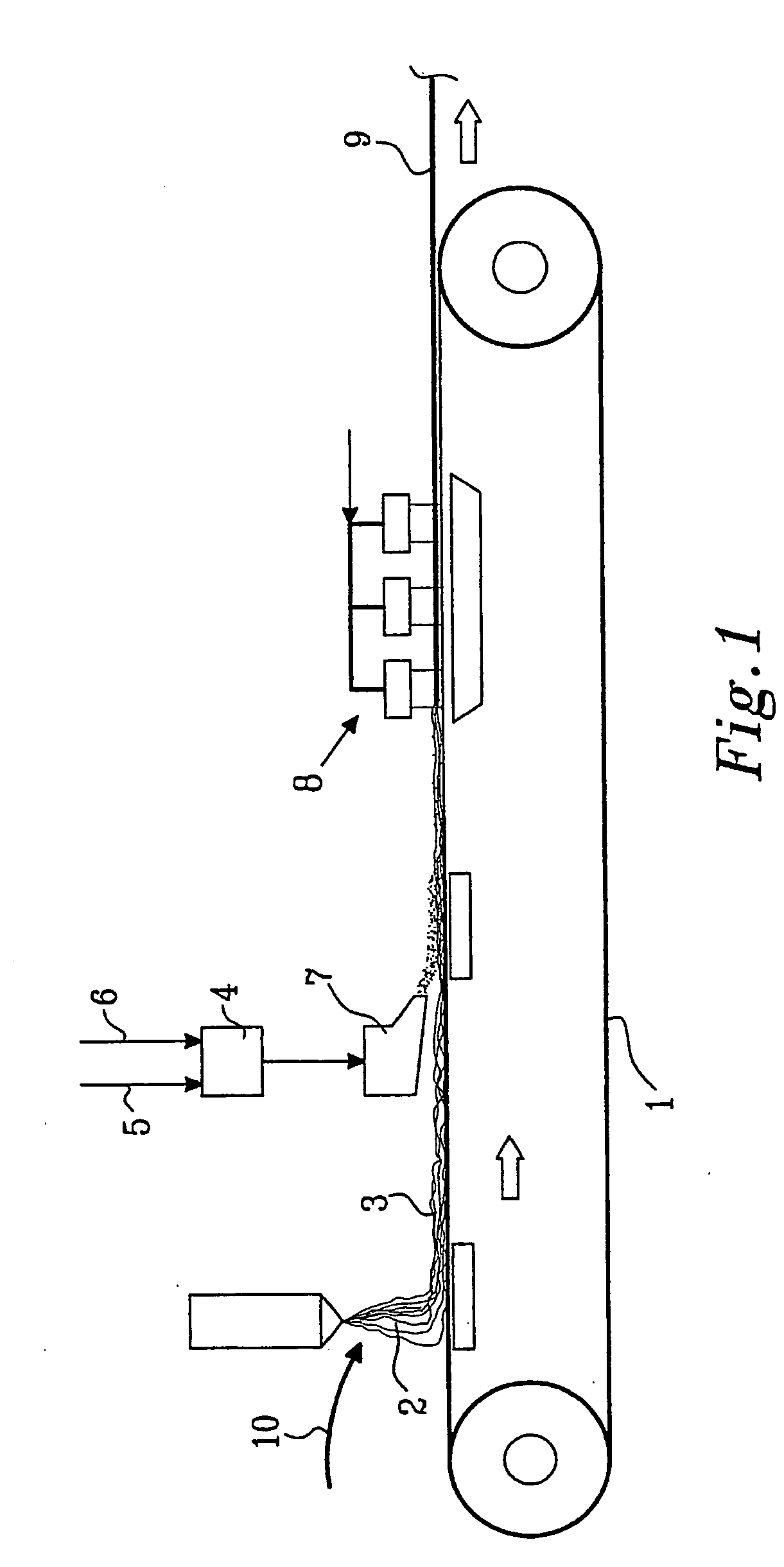
[0118] A 0.4 m wide web of spunlaid filaments was laid down onto a forming fabric at 20 m / min such that the filaments were not bonded to each other. The unbonded web of spunlaid filaments was slightly compacted and transferred to a second forming fabric for addition of the wet-laid components. By a 0.4 m wide headbox a fibre dispersion containing staple fibres and split fibre segments was laid onto the unbonded web of spunlaid filaments and the excess water was drained and sucked off.
[0119] The unbonded spunlaid filaments and wetlaid fibres and fibre segments were then mixed, some of the remaining splittable fibres were split, and the filaments, fibres and fibre segments were bonded together by hydroentanglement with three manifolds at a pressure of 7.0 to 8.0 MPa. The hydroentanglement was done from the side of the web where the wetlaid fibres were laid down and the staple fibres and segments were thus moved into and intensively mixed with the spunlaid filament web. The energy sup...
example 2
[0122] Using the same process as in Example 1, another test was made. The same splittable bicomponent fibre was used, and the titre of the spunlaid filaments was measured to 2.8 dtex. Mixing composition was 50% filaments and 50% splittable fibres. Running speed was 12 m / min, manifold pressure 8.0 MPa and supplied energy about 600 kWh / ton.
example 3
[0123] Using the same process as in Example 1, still another test was made. The same splittable bicomponent fibre was used, and the titre of the spunlaid filaments was measured to 2.8 dtex. Mixing composition was 50% filaments, 25% splittable fibres and 25% polyester staple fibres (from Kuraray) with a length of 12 mm and a titre of 0.5 dtex. Running speed was 12 m / min, manifold pressure 8.0 MPa and supplied energy about 600 kWh / ton.
PUM
| Property | Measurement | Unit |
|---|---|---|
| Length | aaaaa | aaaaa |
| Length | aaaaa | aaaaa |
| Length | aaaaa | aaaaa |
Abstract
Description
Claims
Application Information