Integrated frame battery cell

a battery cell and integrated frame technology, applied in the direction of cell components, sustainable manufacturing/processing, instruments, etc., can solve the problems of reducing the energy density per mass, affecting one of more design factors, and affecting the design of portable computing devices, etc., to achieve the effect of simplifying the assembly process and speeding up the assimilation speed

Active Publication Date: 2011-09-01
APPLE INC
View PDF6 Cites 54 Cited by
  • Summary
  • Abstract
  • Description
  • Claims
  • Application Information

AI Technical Summary

Benefits of technology

[0011]In one aspect, a portable power source and its method of manufacture is described. The portable power source can be used in portable power devices such as but not limited to lap top computers, netbook computers, smart phones and portable media players. The portable power source can include a containment structure for enclosing an electrode and an associated electrolyte in a battery cell, such as a lithium-ion polymer battery cell. The containment structure can prevent leakage of the electrolyte or gasses generated during operation of the portable power source.
[0012]The containment structure can include a rigid frame and a metal foil bonded to the rigid frame where the metal foil encloses a portion of the rigid frame, the electrode assembly and the electrolyte. The rigid frame can protect an electrode, such as edges of the electrode jelly roll, from crush events, which can damage the electrode. To prevent shorts, the metal foil can be coated in plastic, which can insulate the metal foil from the electrode of the battery cell. Further, the plastic can serve as a bonding and sealing agent. For instance, the plastic, via a thermal bonding method, can be melted to bond the metal foil to the rigid frame and to form an air-tight seal for containing a liquid or gel electrolyte associated with the battery cell.
[0013]An electrical connector pad and safety circuitry can be coupled to the rigid frame. The electrical connector pad can allow power to drawn from or added to the portable power source. The safety circuitry can be electrically coupled to the electrical connector pad and the anode and the cathode of the electrode assembly. In particular embodiments, the safety circuitry and the electrical connector pad can be an integral component of the rigid frame or can be provided as a modular component that is coupled to the rigid frame during assembly. Providing the safety circuitry and electrical connector pads in this manner can simplify the assembly process.
[0014]In another embodiment, the rigid frame can include an injector port that allows the electrolyte to be added to the containment structure during assembly of the portable power source. The injector port can be aligned with an axis around which an electrode jelly roll is wound to allow the electrolyte to be injected in an axial direction. Injecting the electrolyte in this manner can allow for a faster assimilation of the electrolyte into the electrode jelly roll as compared to when the electrolyte is injected in a transverse direction.

Problems solved by technology

A design of a portable computing device can involve complex tradeoffs.
A component that is selected on the basis of its positive contribution to one of these design factors can have an adverse impact on one of more other design factors.
First, the energy density per mass will decrease as the mass of the packaging increases.
An inefficiently packaged battery cell can have a lower energy density per volume than an efficiently packaged battery cell.
As the energy density per volume decreases, the volume taken up by the portable power device increases, which can be undesirable for utilization with a portable computing device.

Method used


Image

  • Integrated frame battery cell
  • Integrated frame battery cell
  • Integrated frame battery cell

Examples


Embodiment Construction

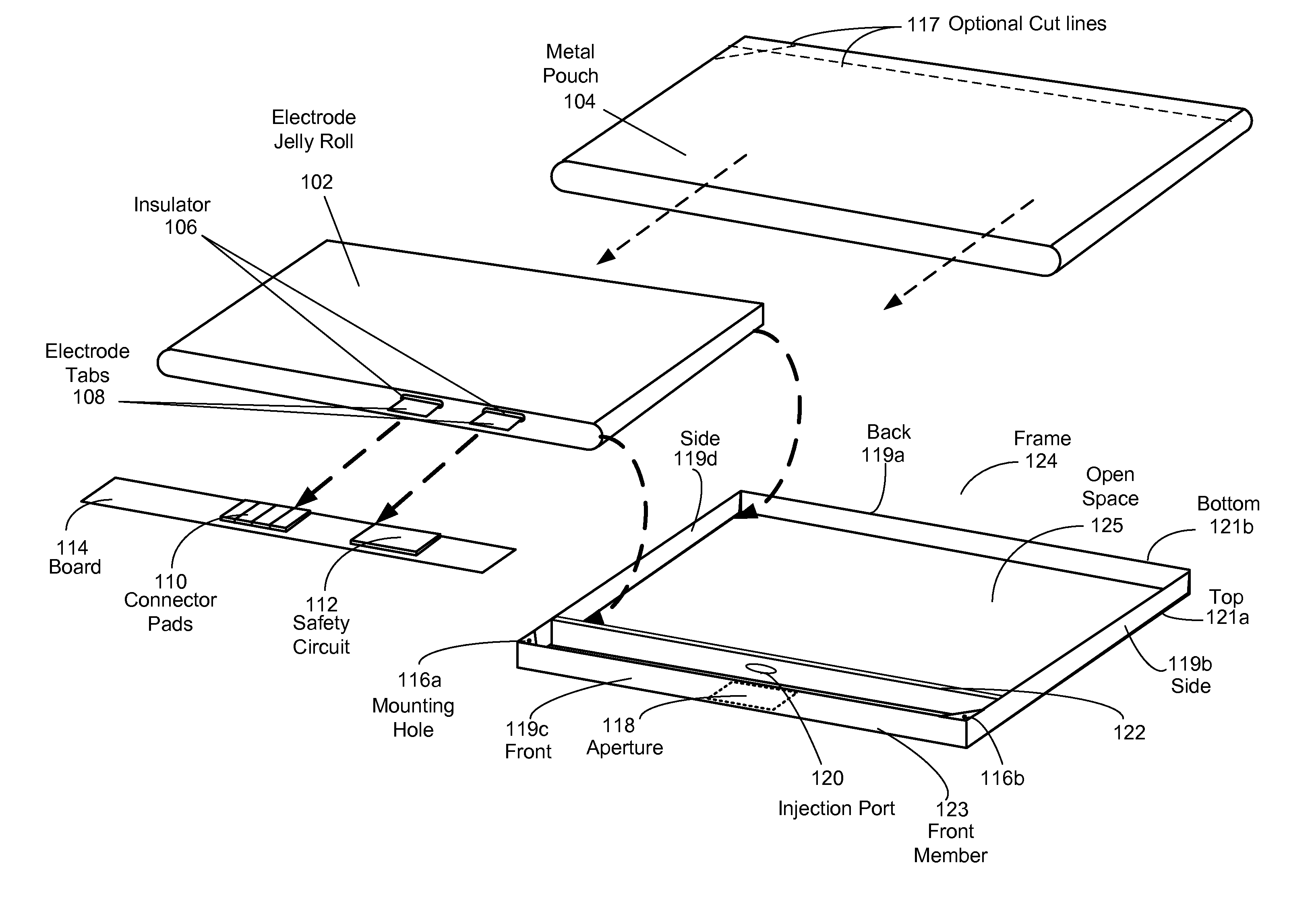
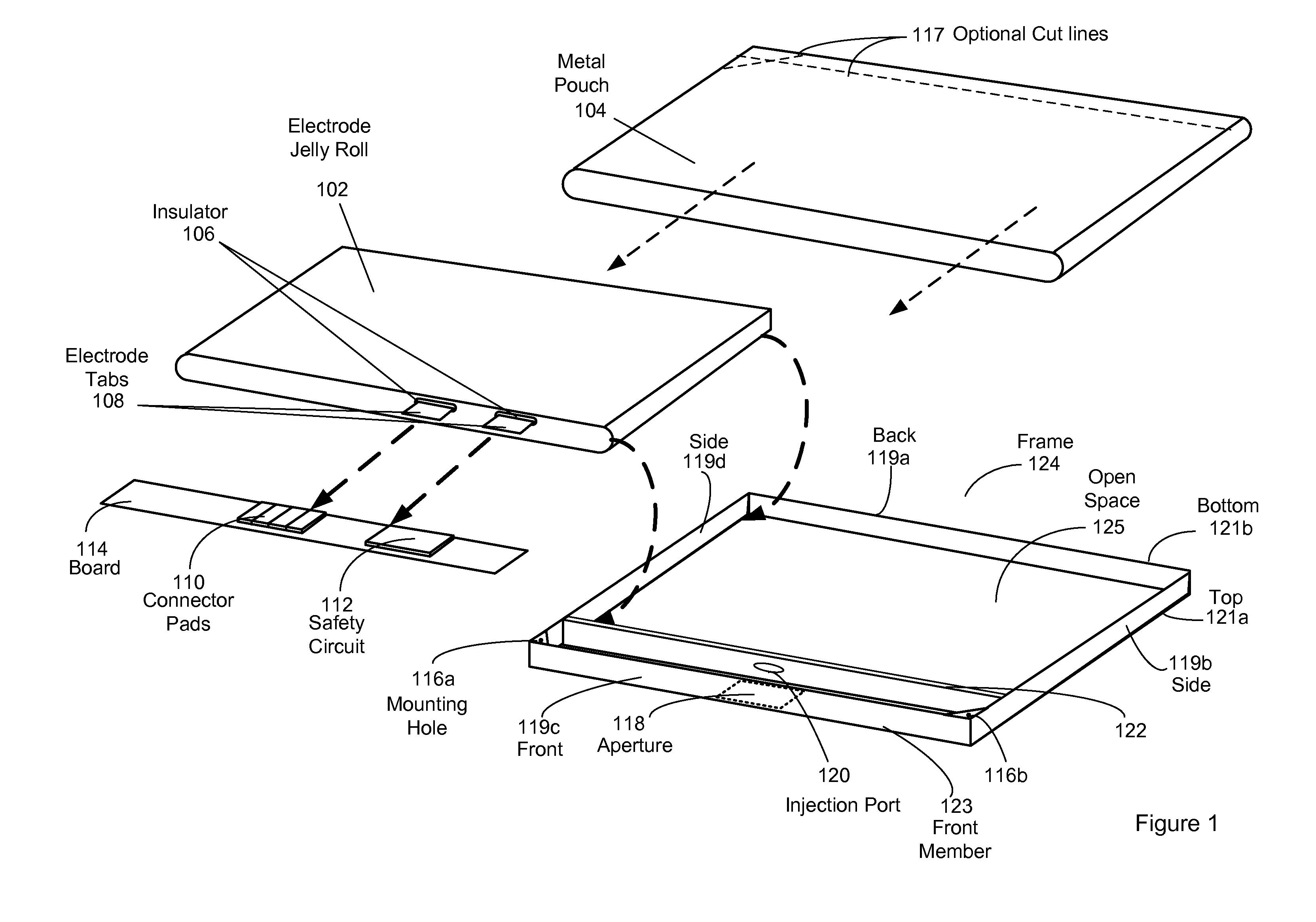
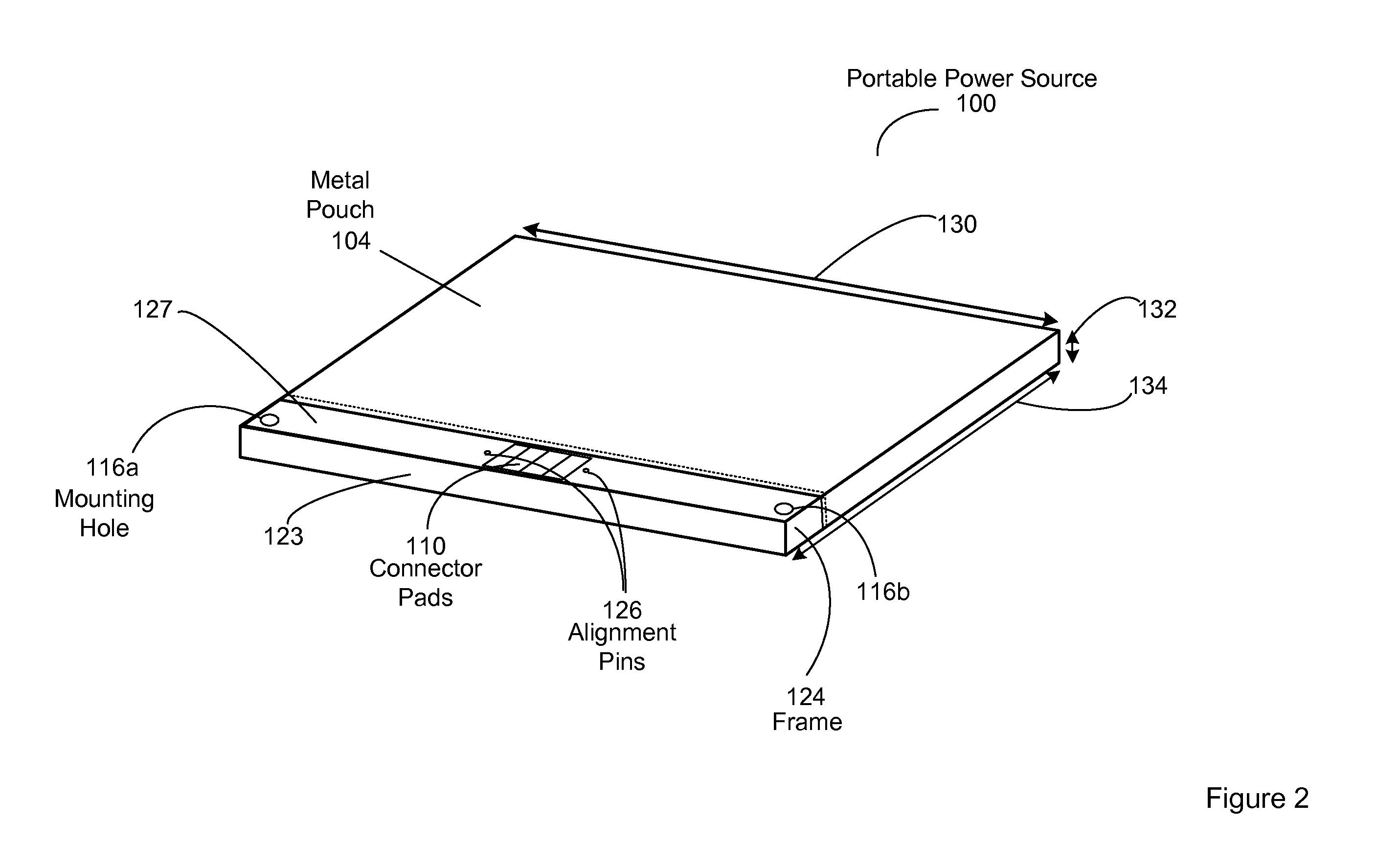
[0010]This paper describes various embodiments that relate to systems, methods, and apparatus for enclosures for use in portable computing applications.

[0011]In one aspect, a portable power source and its method of manufacture is described. The portable power source can be used in portable power devices such as but not limited to lap top computers, netbook computers, smart phones and portable media players. The portable power source can include a containment structure for enclosing an electrode and an associated electrolyte in a battery cell, such as a lithium-ion polymer battery cell. The containment structure can prevent leakage of the electrolyte or gasses generated during operation of the portable power source.

[0012]The containment structure can include a rigid frame and a metal foil bonded to the rigid frame where the metal foil encloses a portion of the rigid frame, the electrode assembly and the electrolyte. The rigid frame can protect an electrode, such as edges of the elect...


PUM

PropertyMeasurementUnit
thickaaaaaaaaaa
thickaaaaaaaaaa
thickaaaaaaaaaa

Abstract

An electrolyte containment structure for an electrode jelly roll and electrolyte in a portable power source is described. The electrolyte containment structure comprises metal foil, such as metal foil sleeve, coupled to and partially surrounding a rigid frame. The rigid frame can protect the electrode jelly roll edges from crush events. To prevent shorts, the metal foil can be coated in plastic, which can insulate the metal foil from the electrode jelly roll. Further, the plastic can serve as a bonding and sealing agent. For instance, the metal foil can be coupled to the rigid frame using a thermal bonding method involving melting of the plastic. The rigid frame can provide a platform for connector pads and safety circuitry associated with the portable power source. The connector pads and safety circuitry can be assembled as modular components, which can simplify the assembly process The containment structure provides features associated with a pouch cell battery design, such as a light-weight metal foil pouch, but can be utilized in a portable computing device without being enclosed in a hard casing traditionally associated with pouch cell battery designs.

Description

BACKGROUND OF THE INVENTION[0001]1. Field of the Invention[0002]The described embodiments relate generally to batteries for portable computing devices. More particularly, the present embodiments relate to battery packaging designs for portable computing devices.[0003]2. Description of the Related Art[0004]A design of a portable computing device can involve complex tradeoffs. A few factors that can be considered in the design process are cosmetic appeal, weight, manufacturability, durability, thermal compatibility and power consumption. A component that is selected on the basis of its positive contribution to one of these design factors can have an adverse impact on one of more other design factors.[0005]A portable power source, typically, a battery of some type is an important component in the design of a portable computing device. The portable power source provides operating power for the portable computing device when it is not near a fixed power source, such as a wall outlet. Fac...

Claims


Application Information

Patent Timeline
Patent Type & Authority Applications(United States)
IPC IPC(8): G06F3/038H01M2/02B23K31/02B32B38/00H01M50/119H01M50/124H01M50/55
CPCH01M10/0525H01M10/425Y02E60/122H01M2/1027H01M2/0277H01M2/0285H01M2/0287H01M2/0215Y02E60/10H01M50/124H01M50/267Y02P70/50H01M50/55H01M50/119H01M10/42
Inventor MURPHY, R. SEANWILSON, JR., THOMAS W.
Owner APPLE INC
Why Eureka
Try Eureka