Method for streamline traced external compression inlet

a compression inlet and traced technology, applied in the direction of machines/engines, air-flow influencers, rotors, etc., can solve the problems of poor engine performance, increased weight, increased mechanical complexity and maintenance costs of aircraft, and increased weight of aircraft, so as to reduce cowl drag, the effect of easy prediction of performance and desired internal flow field and inlet performan

Inactive Publication Date: 2007-08-09
LOCKHEED MARTIN CORP
View PDF23 Cites 22 Cited by
  • Summary
  • Abstract
  • Description
  • Claims
  • Application Information

AI Technical Summary

Benefits of technology

[0011] Streamline tracing the cowl allows for alternate aperture shaping to be employed while producing the desired spillage and minimizing cowl drag, while maintaining the desired internal flow field and inlet performance. Without this technique, 3D shaped external compression inlets would require more extensive testing and design iterations to predict and optimize their performance. The techniques provided by embodiments of t...

Problems solved by technology

This low energy air can cause poor engine performance.
However, air induction systems often require complex subsystems in order to work properly at high speed.
As such, these air inductions systems increase the weight, cost of production, mechanical complexity and cost of maintenance o...

Method used


Image

  • Method for streamline traced external compression inlet
  • Method for streamline traced external compression inlet
  • Method for streamline traced external compression inlet

Examples


Embodiment Construction

[0026] Preferred embodiments of the present invention are illustrated in the FIGs., like numerals being used to refer to like and corresponding parts of the various drawings.

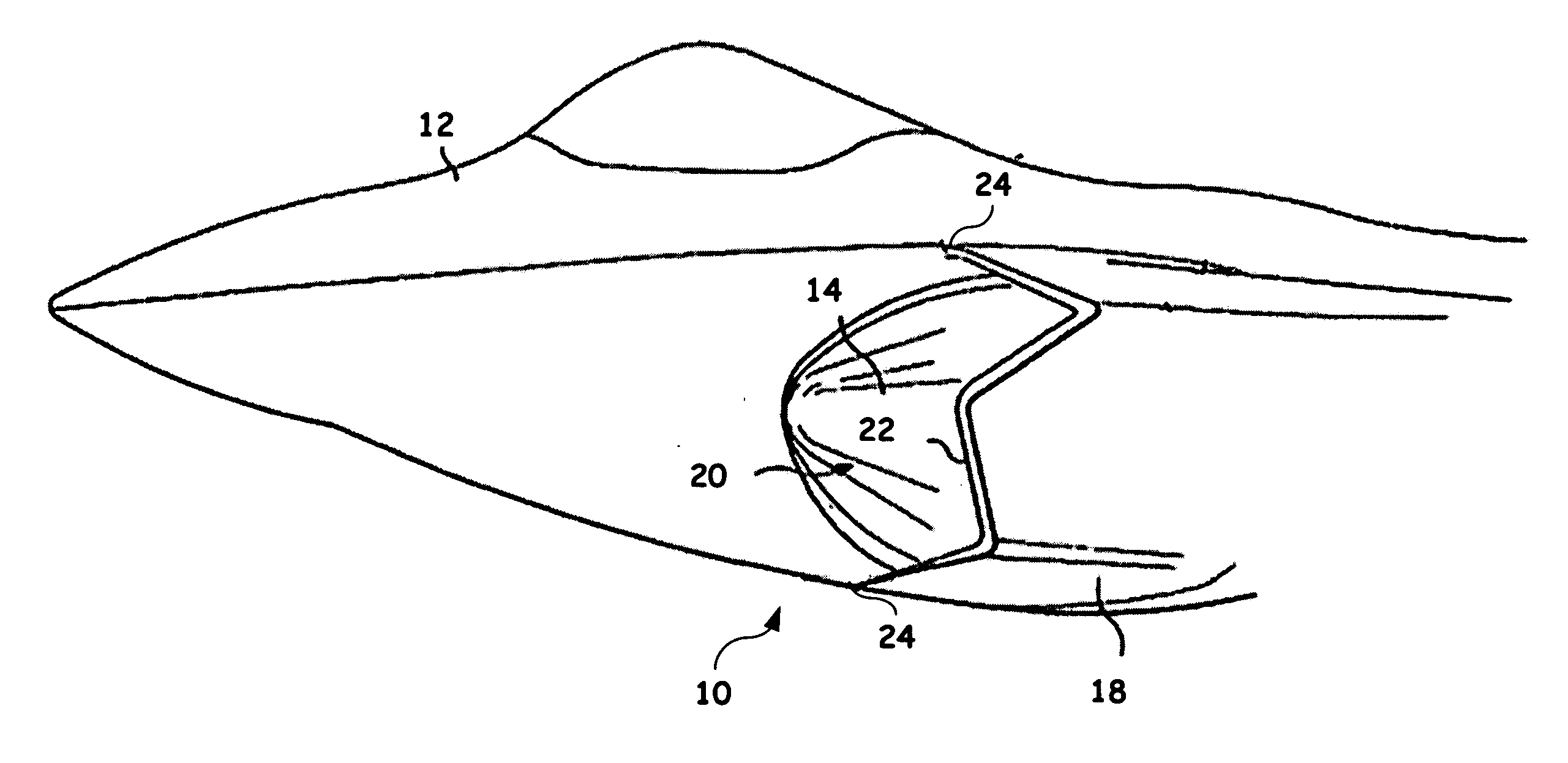
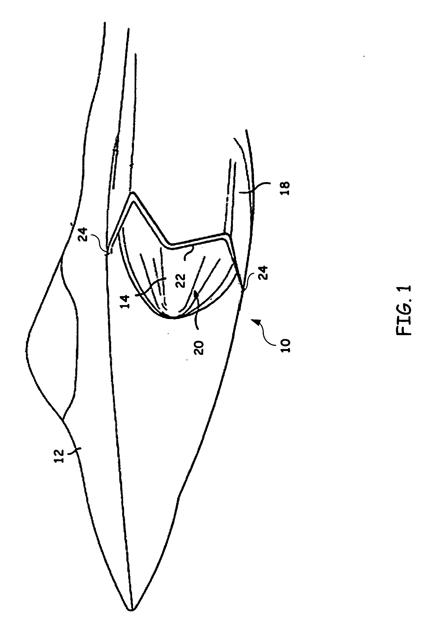
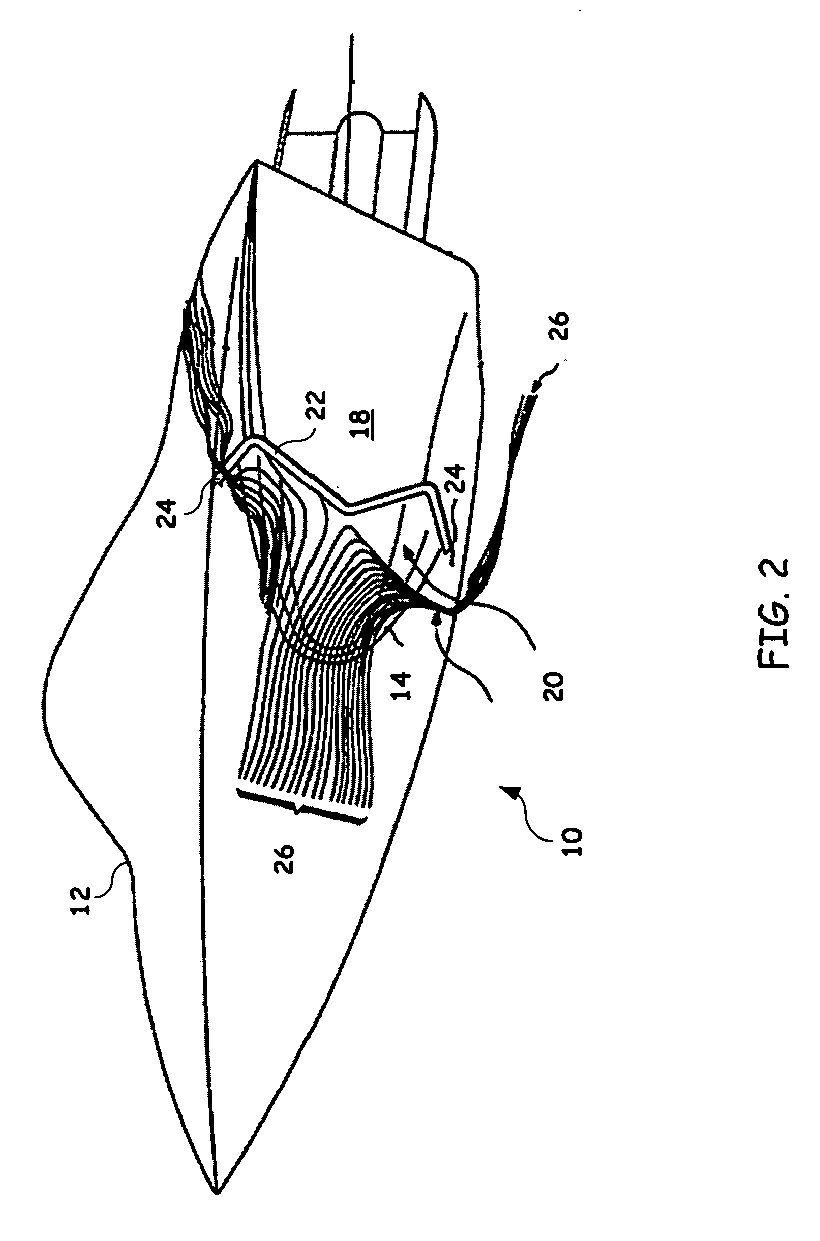
[0027] Historic external compression air induction systems for gas turbine powered supersonic aircraft do not meet the current needs for inlet / airframe integration. These needs are driven by factors such as tailored aperture shapes, drag minimization, and propulsion performance. Embodiments of the present invention provide a method to create a Streamline Traced External Compression Inlet (STECI) that substantially addresses Inlet / Airframe integration issues. This method results in fewer design iterations than traditional historic external compression inlets.

[0028] Historical supersonic external compression inlets are based on simple 2D ramp or Axisymmetric configurations, or have been designed using Caret shaping or Diverterless Supersonic Inlet methodologies. None of these historical configurations or methods...


PUM


Abstract

Embodiments of the present invention provide a Streamline Traced External Compression Inlet (STECI) that represents a new solution to external compression inlet integration issues. STECI utilizes a Computational Fluid Dynamics (CFD) solution produced by a shock-generating shape which is defined by a conceptual design trade study. The shock generating shape may be created by single or multiple surfaces depending on number of upstream oblique shocks required to produce desired flow characteristics at the throat of the inlet. An aperture is then defined according to shaping requirements. This desired aperture is projected onto the forward-most, and aft-most oblique shocks of the flow field. The projected cowl portion of the aperture is then offset downstream from the aft-most oblique shock to allow for air to be “spilled” by the inlet. The resultant shape of the projected/offset cowl and the projected compression surface leading edge is the STECI aperture. Streamline seeds are placed along the STECI aperture and are used to produce streamlines through the CFD solution (which represents a physical flow field). These streamlines provide the basis for the surfaces that make up the portion of the STECI from the leading edge of the bump surface to the inlet throat and the tangencies for surfaces that will exist downstream of the throat. Traditional methods are used to define and loft the subsonic diffuser from the inlet aperture to the engine face.

Description

TECHNICAL FIELD OF THE INVENTION [0001] The present invention relates generally to engine inlet design, and more particularly, external compression inlet integration within aircraft design. BACKGROUND OF THE INVENTION [0002] Low velocity, low pressure, boundary layer air (i.e., low energy air) builds up on the fuselage of a supersonic aircraft in front of the main engine inlets during high speed flight. This low energy air can cause poor engine performance. To address this problem, high-speed aircraft have traditionally employed boundary layer diverter systems to prevent low energy air from entering the air inlet. However, air induction systems often require complex subsystems in order to work properly at high speed. As such, these air inductions systems increase the weight, cost of production, mechanical complexity and cost of maintenance of the aircraft. [0003] Air inlet systems for gas turbine powered supersonic aircraft decelerate the approaching flow to subsonic conditions prio...

Claims


Application Information

Patent Timeline
IPC IPC(8): B64C21/10
CPCB64C21/10B64D33/02F01D5/148F01D7/00F05D2220/80Y02T50/166Y02T50/671Y02T50/673F02C7/00Y02T50/10Y02T50/60
Inventor KLINGE, JOHN D.SUCHER, MATTHEW D.MESSINA, TODD L.
Owner LOCKHEED MARTIN CORP
Why Eureka
Try Eureka