Organic light emitting display providing ultraviolet ray protection and method of manufacturing same

a technology of organic light and ultraviolet radiation, applied in the direction of water/sewage multi-stage treatment, water separation process, water treatment multi-stage treatment, etc., can solve the problems of difficult structure, complicated manufacturing process, and inability to meet the requirements of ultraviolet radiation curing, so as to prevent moisture and oxygen penetration

Active Publication Date: 2007-08-09
SAMSUNG DISPLAY CO LTD
View PDF2 Cites 58 Cited by
  • Summary
  • Abstract
  • Description
  • Claims
  • Application Information

AI Technical Summary

Benefits of technology

[0018]According to another exemplary embodiment of the present invention, a method of manufacturing an organic light emitting display including an ultraviolet protecting layer is provided. The method includes: forming an ultraviolet hardening adhesive on a lower substrate; depositing a driving unit and a light emitting unit on the lower substrate and surrounded by the ultraviolet hardening adhesive; covering the driving unit and light emitting unit with an encapsulation layer preventing moisture and oxygen penetration from an outside; arranging an upper substrate on the encapsulation layer facing the lower substrate; forming an ultraviolet ray blocking film in a region to block the driving unit and the light emitting unit from being irradiated by UV rays; radiating the ultraviolet hardening adhesive with UV rays to harden the ultraviolet hardening adhesive and fix the upper substrate with the lower substrate.

Problems solved by technology

However, since the separate shading mask has to be prepared, the manufacturing process is very complicated.
Accordingly, the processes of both making the shading mask and positioning the shading mask on the upper substrate 15 complicate the UV curing process.
However, such a structure is not always possible and is possible only in the case of a so-called can type substrate in which a hollow space accommodating the hygroscopic agent is prepared.
Thus, the whole manufacturing process is complicated since a separate process of preparing the hydroscopic agent and an assembly process, in addition to the film formation processes, are required as when using the conventional shading mask.

Method used


Image

  • Organic light emitting display providing ultraviolet ray protection and method of manufacturing same
  • Organic light emitting display providing ultraviolet ray protection and method of manufacturing same
  • Organic light emitting display providing ultraviolet ray protection and method of manufacturing same

Examples


Embodiment Construction

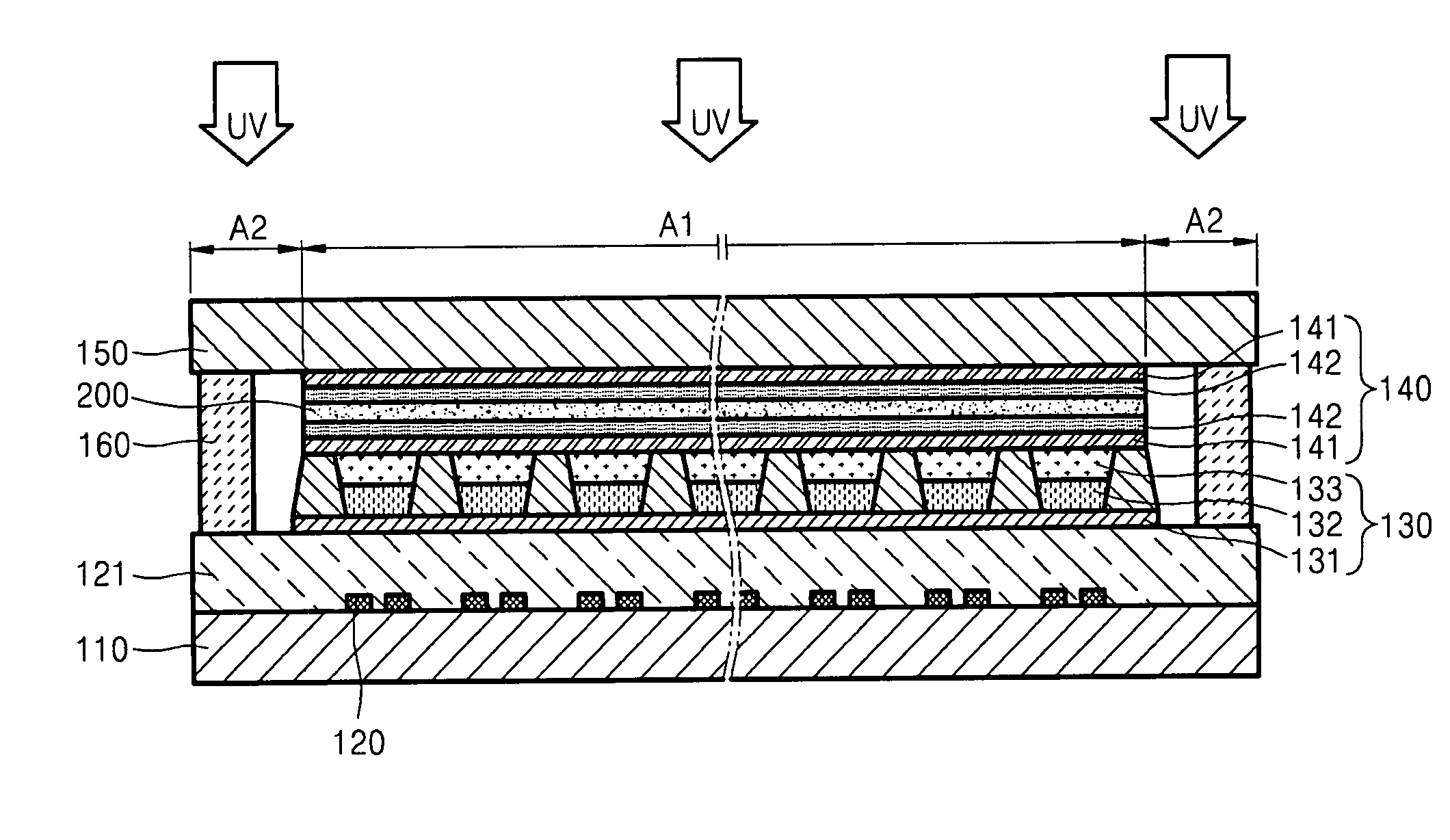
[0024]Hereinafter, the present invention will be described more fully with reference to the accompanying drawings, in which exemplary embodiments of the invention are shown. This invention may, however, be embodied in many different forms and should not be construed as limited to the exemplary embodiments set forth herein. Rather, these embodiments are provided so that this disclosure will be thorough and complete, and will fully convey the scope of the invention to those skilled in the art. In the drawings, lengths and sizes of layers and regions may be exaggerated for clarity.

[0025]It will be understood that when an element or layer is referred to as being “on” another element or layer, the element or layer can be directly on another element or layer or intervening elements or layers. In contrast, when an element is referred to as being “directly on” another element or layer, there are no intervening elements or layers present. Like numbers refer to like elements throughout. As us...


PUM

PropertyMeasurementUnit
structureaaaaaaaaaa
flexibilityaaaaaaaaaa
areaaaaaaaaaaa

Abstract

An organic light emitting display including an ultraviolet protecting layer and a method of manufacturing the same include a lower substrate; an ultraviolet hardening adhesive formed on the lower substrate; a driving unit and a light emitting unit deposited on the lower substrate and surrounded by the ultraviolet hardening adhesive; an encapsulation layer covering the driving unit and light emitting unit and preventing moisture and oxygen penetration from an outside; an upper substrate arranged on the encapsulation layer facing the lower substrate and fixed by the ultraviolet hardening adhesive; and an ultraviolet ray blocking film formed in a region to block the driving unit and the light emitting unit from being irradiated by UV rays radiated to harden the ultraviolet hardening adhesive. The ultraviolet ray blocking film is disposed in the encapsulation layer or on the upper substrate to protect the driving unit and light emitting unit from ultraviolet rays.

Description

[0001]This application claims priority to Korean Patent Application No. 10-2006-0010593, filed on Feb. 3, 2006, and all the benefits accruing therefrom under 35 U.S.C. §119, and the contents of which in its entirety are herein incorporated by reference.BACKGROUND OF THE INVENTION[0002]1. Field of the Invention[0003]The present invention relates to an organic light emitting display and method, and more particularly, to an organic light emitting display providing an ultraviolet ray protection function and method of manufacturing the same.[0004]2. Description of the Related Art[0005]Generally, organic light emitting displays include organic light emitting diodes (“OLEDs”) deposited on thin film transistors (“TFTs”) of an electric circuit so that a light emitting layer of a selected OLED emits light in response to a signal controlled by the TFT.[0006]FIG. 1 shows the typical structure of such an organic light emitting display. As described above, a TFT 12 as a driving unit and an OLED 1...

Claims


Application Information

Patent Timeline
Patent Type & Authority Applications(United States)
IPC IPC(8): H01J1/62
CPCH01L27/3244H01L51/5256H05B33/22H10K59/12H10K50/8445B01D29/50C02F1/28C02F9/00C02F2301/08C02F2103/20
Inventor OH, TAE-SIKLEE, YOUNG-GUKANG, SUNG-KEEKO, ICK-HWANCHUN, YOUNG-TEASHIM, HONG-SHIK
Owner SAMSUNG DISPLAY CO LTD
Why Eureka
Try Eureka