Electromagnetic wave generating device

a generation device and electromagnetic technology, applied in the direction of oscillator generators, electric discharge tubes, accelerators, etc., can solve the problems of increasing the capacity and size of the power supply of the focusing coil and the electromagnet, reducing the volume of the vacuum chamber, and increasing the loss of electron beams, so as to achieve the effect of small size and small power supply capacity

Inactive Publication Date: 2007-08-09
MITSUBISHI ELECTRIC CORP
View PDF5 Cites 11 Cited by
  • Summary
  • Abstract
  • Description
  • Claims
  • Application Information

AI Technical Summary

Benefits of technology

The technical effect of this patent is to create an electromagnetic wave generator that is small and uses less power than previous versions.

Problems solved by technology

The technical problem addressed in this patent text is the limitations of conventional electromagnetic wave generating devices that use betatron accelerators. These devices require separate focusing and accelerating coils, which leads to problems such as reduced vacuum chamber volume and increased device size. There is also a need for a more efficient and compact accelerating magnet.

Method used


Image

  • Electromagnetic wave generating device
  • Electromagnetic wave generating device
  • Electromagnetic wave generating device

Examples


embodiment 1

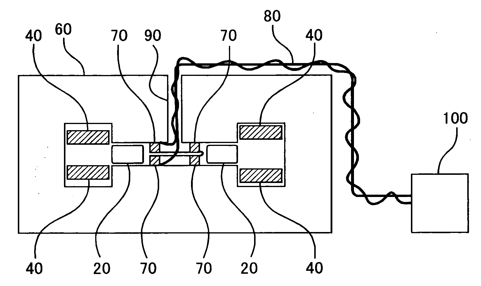
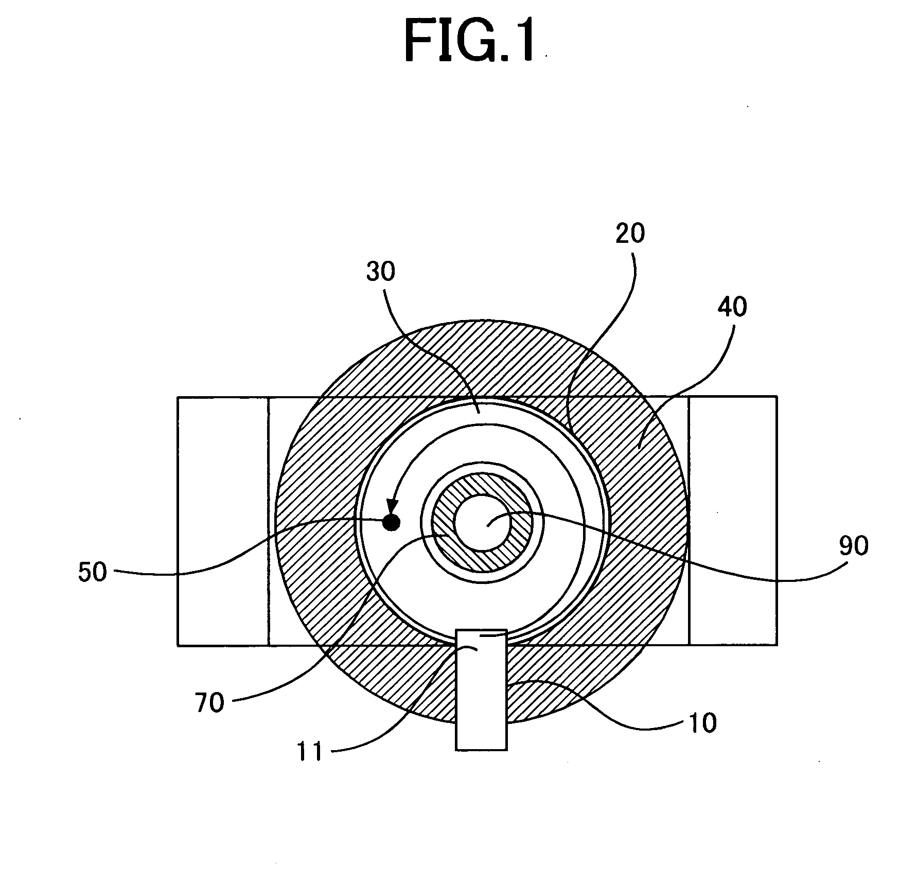
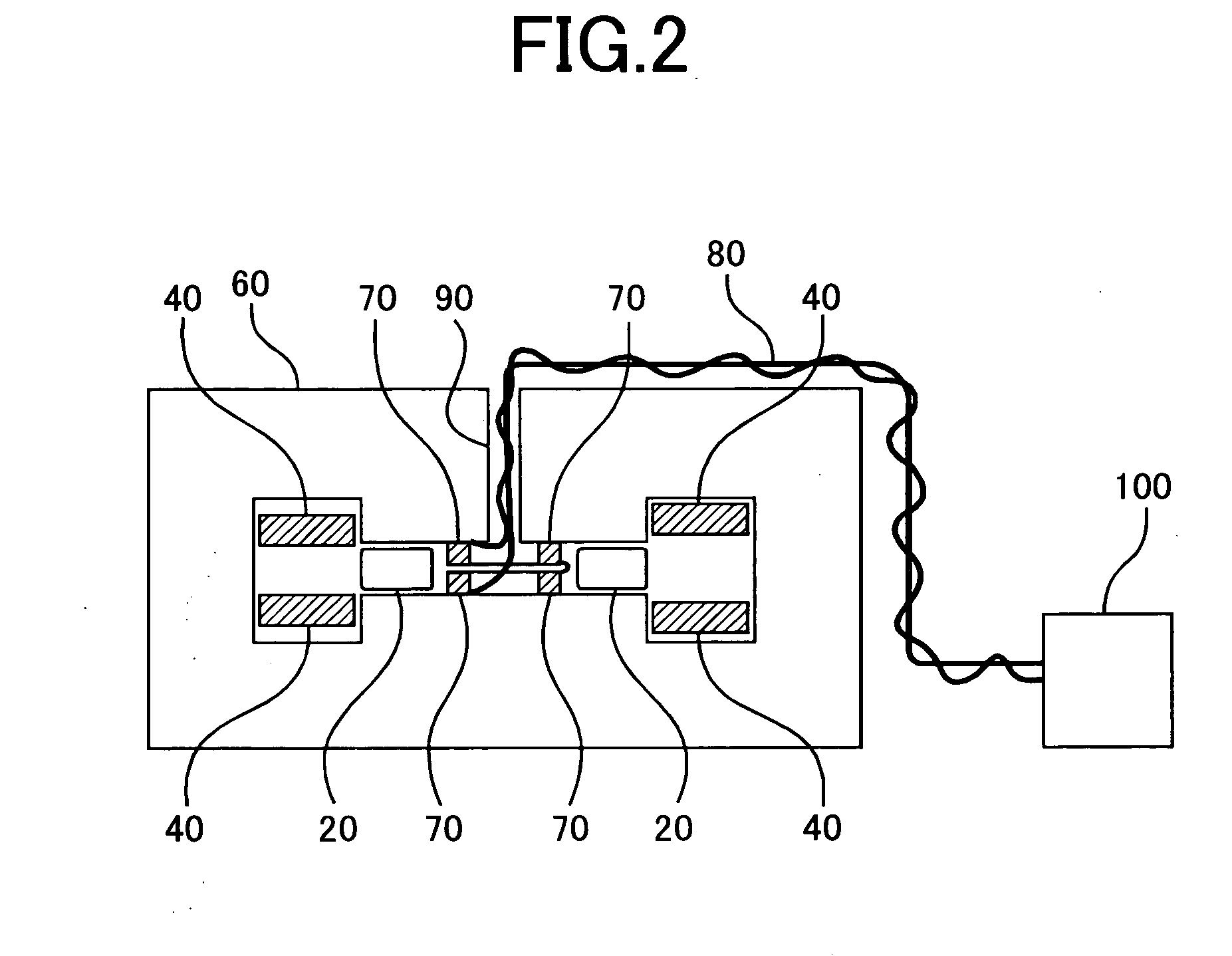
[0024]FIG. 1 and FIG. 2 illustrate an electromagnetic wave generating device according to Embodiment 1 of the present invention, and FIG. 1 is a horizontal sectional view and FIG. 2 is a vertical sectional view.

[0025]Referring to FIG. 1, an electron emitting portion 11 of an electron gun 10 is disposed inside a vacuum chamber 20, for emitting an electron beam 30 from the electron emitting 11 into the vacuum chamber 20. The emitted electron beam 30 revolves in a circular orbit indicated in FIG. 1, by focusing magnetic flux generated by focusing coils 40, and impacts a target 50 to emit an electromagnetic wave.

[0026]The vacuum chamber 20 has a hollow annular structure, and the inside thereof is maintained under high vacuum so that the electron beam 30 revolves cyclically in the circular orbit. The cross section of the chamber 20 is formed in a rectangular shape elongated radially to make allowance for some fluctuations in the orbital radius of the electron beam 30.

[0027]An electromagn...


PUM


Abstract

An electromagnetic wave generating device includes: a hollow annular vacuum chamber; an electron gun; an electromagnet configured with a pair of discoid combinations in which a cylindrical accelerating magnet pole and an annular focusing magnet pole are arranged in this order from the inner side to the outer side of the combinations, and are disposed symmetrically and concentrically with each other on both sides of the chamber and coaxially with the center axis of the chamber, and a return yoke disposed outside both accelerating and focusing magnet poles and the chamber; accelerating coils wound around the accelerating magnet poles, for exciting the poles; and focusing coils wound around the focusing magnet poles, for exciting the poles; wherein a through hole is formed at the center of the accelerating magnet pole so that power supply wires connecting the accelerating coils to an accelerating power supply are led out through the hole.

Description


Claims


Application Information

Patent Timeline
Owner MITSUBISHI ELECTRIC CORP
Why Eureka
Try Eureka