Image display device and image display method

a technology of image display device and image, which is applied in the direction of static indicating device, cathode-ray tube indicator, instruments, etc., can solve the problems of impulse-type display flicker, image appears blurred, waste of power consumption of backlight which is illuminated during black display as well as other problems, to achieve the effect of improving the quality of moving image and still image displayed on the image display devi

Inactive Publication Date: 2007-08-09
KK TOSHIBA
View PDF11 Cites 58 Cited by
  • Summary
  • Abstract
  • Description
  • Claims
  • Application Information

AI Technical Summary

Benefits of technology

[0023] According to the present invention, the quality of the moving image and the still image displayed on the image display device can be improved as much as possible while restraining increase in power consumption and the flicker.

Problems solved by technology

However, the liquid crystal display device and the organic EL display have a problem such that the image appears to be blurred when the moving image is displayed.
This problem is caused by the fact that temporal characteristics of an image display method are different between the liquid crystal display device or the organic EL display and the CRT.
However, the power consumption of a backlight which is illuminated during the black display as well is wasteful.
In the still image display, there is a problem that flicker caused by the impulse-type display occurs.
Therefore, a sufficient reduction of power consumption cannot be achieved.
In this case, however, the quality of the moving image is lowered.
In addition, there is a problem such that an abrupt change in ratio of black display period (black display period / one frame period) such as the switching between the impulse-type display and the hold-type display is viewed by the observer as the flicker, and hence the lowering of the image quality is resulted.

Method used


Image

  • Image display device and image display method
  • Image display device and image display method
  • Image display device and image display method

Examples


first embodiment

[0040] Referring now to FIG. 1 to FIG. 9, a liquid crystal display device 10 according to a first embodiment of the invention will be described.

[0041] (1) Configuration of the liquid crystal display device

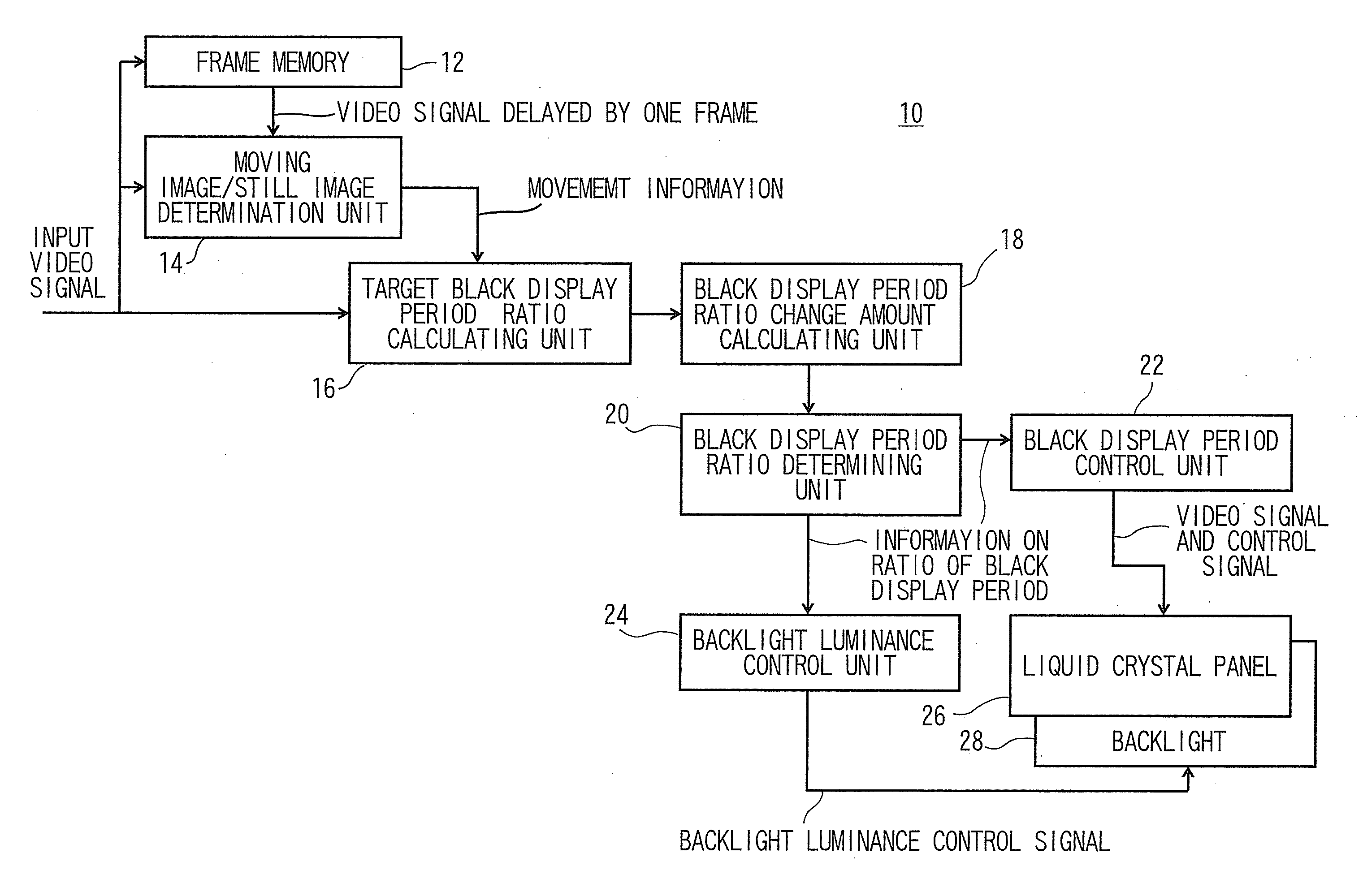
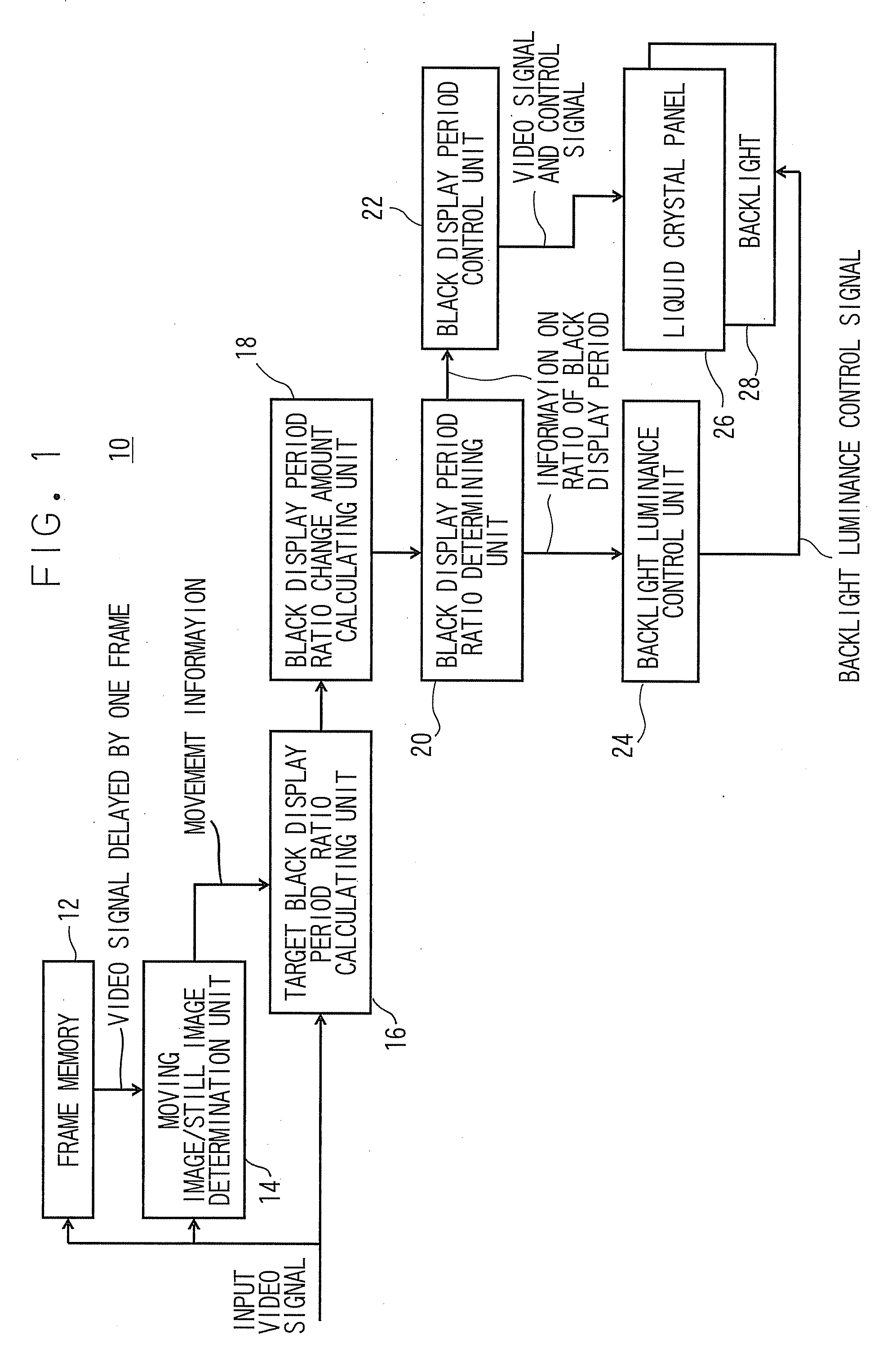
[0042]FIG. 1 shows a configuration of the liquid crystal display device 10.

[0043] An input video signal is supplied to a frame memory 12, a moving image / still image determination unit 14, and a target black display period ratio calculating unit 16.

[0044] The frame memory 12 holds the input video signal for one frame period, and outputs the same to the moving image / still image determination unit 14 as a video signal delayed by one frame. The term “one frame” corresponds to a piece of image displayed on the liquid crystal display device 10, and the term “one field” which is generally referred regarding an interlace video signal and the term “one frame” here are identical.

[0045] The moving image / still image determination unit 14 detects a magnitude of the movement between tempora...

second embodiment

[0126] Subsequently, the liquid crystal display device 10 according to the second embodiment will be described.

[0127] The basic configuration of the liquid crystal display device 10 in this embodiment is the same as the one in the first embodiment. However, the operation of the target black display period ratio calculating unit 16 and the black display period ratio change amount calculating unit 18 is different from that of the first embodiment.

[0128] The target black display period ratio calculating unit 16 calculates the discrete target ratios of black display period by Expression 3 as in the first embodiment. However, the redundancy is not provided to the threshold value as in the first embodiment, and is a fixed value. In this embodiment, the discrete target ratios of black display period are calculated by applying the threshold processing to the target ratio of black display period. However, the above-described discretization is not essential, and the target ratio of black di...

third embodiment

[0137] Subsequently, the liquid crystal display device 10 according to the third embodiment will be described.

[0138] The basic configuration of the liquid crystal display device 10 in this embodiment is the same as the one in the first embodiment. However, the operation of the target black display period ratio calculating unit 16 and the black display period ratio change amount calculating unit 18 is different from that of the first embodiment.

[0139] The target black display period ratio calculating unit 16 calculates the discrete target ratios of black display period by Expression 3 as in the first embodiment. However, the redundancy is not provided to the threshold value as in the first embodiment, and is a fixed value.

[0140] In this embodiment, the discrete target ratios of black display period are calculated by applying the threshold processing to the target ratio of black display period. However, the above-described discretization is not essential, and the target ratio of bl...


PUM


Abstract

A liquid crystal panel for displaying an input image and a black image during one frame period, a target black display period ratio calculating unit configured to obtain a black image display period occupying one frame period of the input image, a black display period ratio change amount calculating unit configured to obtain the amount of change in ratio of black display period for each of one or a plurality of frames, a black display period ratio determining unit configured to calculate the ratio of black display period for an actual display, a black display period control unit configured to control a period for displaying the input image and the black image on the image display unit, and a display luminance control unit configured to restrain variations in luminance of the image display unit during one frame period within a predetermined range are provided.

Description

CROSS-REFERENCE TO RELATED APPLICATIONS [0001] This application is based upon and claims the benefit of priority from the prior Japanese Patent Application No. 2006-28924, filed on Feb. 6, 2006; the entire contents of which are incorporated herein by reference. TECHNICAL FIELD [0002] The present invention relates to an image display device in which the quality of a moving image and a still image is improved while restraining increase in power consumption. BACKGROUND OF THE INVENTION [0003] In recent years, a technical advancement of a flat panel display device such as liquid crystal display device or an organic EL (Electro Luminescence) display has been in progress, and it starts to be generalized in a TV field in which a cathode ray tube (hereinafter, referred to as CRT) has been a mainstream technology. [0004] However, the liquid crystal display device and the organic EL display have a problem such that the image appears to be blurred when the moving image is displayed. This probl...

Claims


Application Information

Patent Timeline
Patent Type & Authority Applications(United States)
IPC IPC(8): G09G3/36
CPCG09G3/20G09G3/342G09G3/3648G09G2310/024G09G2310/061G09G2360/18G09G2320/0261G09G2320/0633G09G2320/0646G09G2320/103G09G2340/16G09G2320/0247G09G3/36G09G5/00
Inventor BABA, MASAHIROITOH, GOH
Owner KK TOSHIBA
Why Eureka
Try Eureka