Touch panel

Inactive Publication Date: 2007-08-09
PANASONIC CORP
View PDF7 Cites 134 Cited by
  • Summary
  • Abstract
  • Description
  • Claims
  • Application Information

AI Technical Summary

Benefits of technology

[0021]The touch panel of the present invention includes a first substrate of optical transparency, a second substrate of optical transparency, a wiring substrate, and an anisotropic conductive adhesive layer. The first substrate has a first surface, a first conductive layer formed at the first surface, and first electrodes formed in a manner to extend from two opposite sides of the first conductive layer. The second substrate has a second surface, a second conductive layer formed at the second surface in a manner to confront the first surface with a space, and second electrodes formed in a manner to extend from two opposite sides of the second conductive layer in a direction ort

Problems solved by technology

Such a phenomenon of short-circuiting, if occurs, may impair the electrical insulation between the electrodes or the wiring patterns, thereby resulting in insta

Method used


Image

  • Touch panel
  • Touch panel
  • Touch panel

Examples


Example

[0034]Description is provided hereinafter of an exemplary embodiment of the present invention with reference to FIG. 1 to FIG. 7.

Exemplary Embodiment

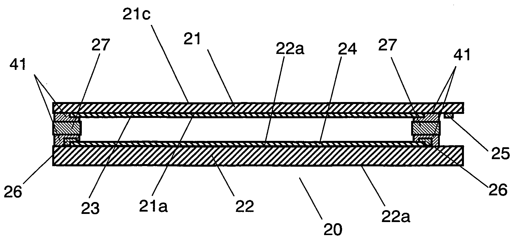
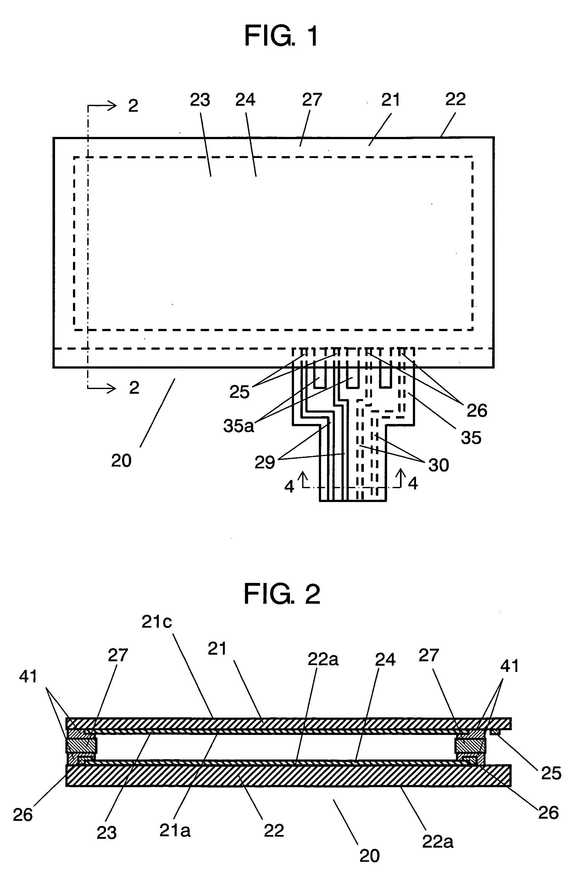
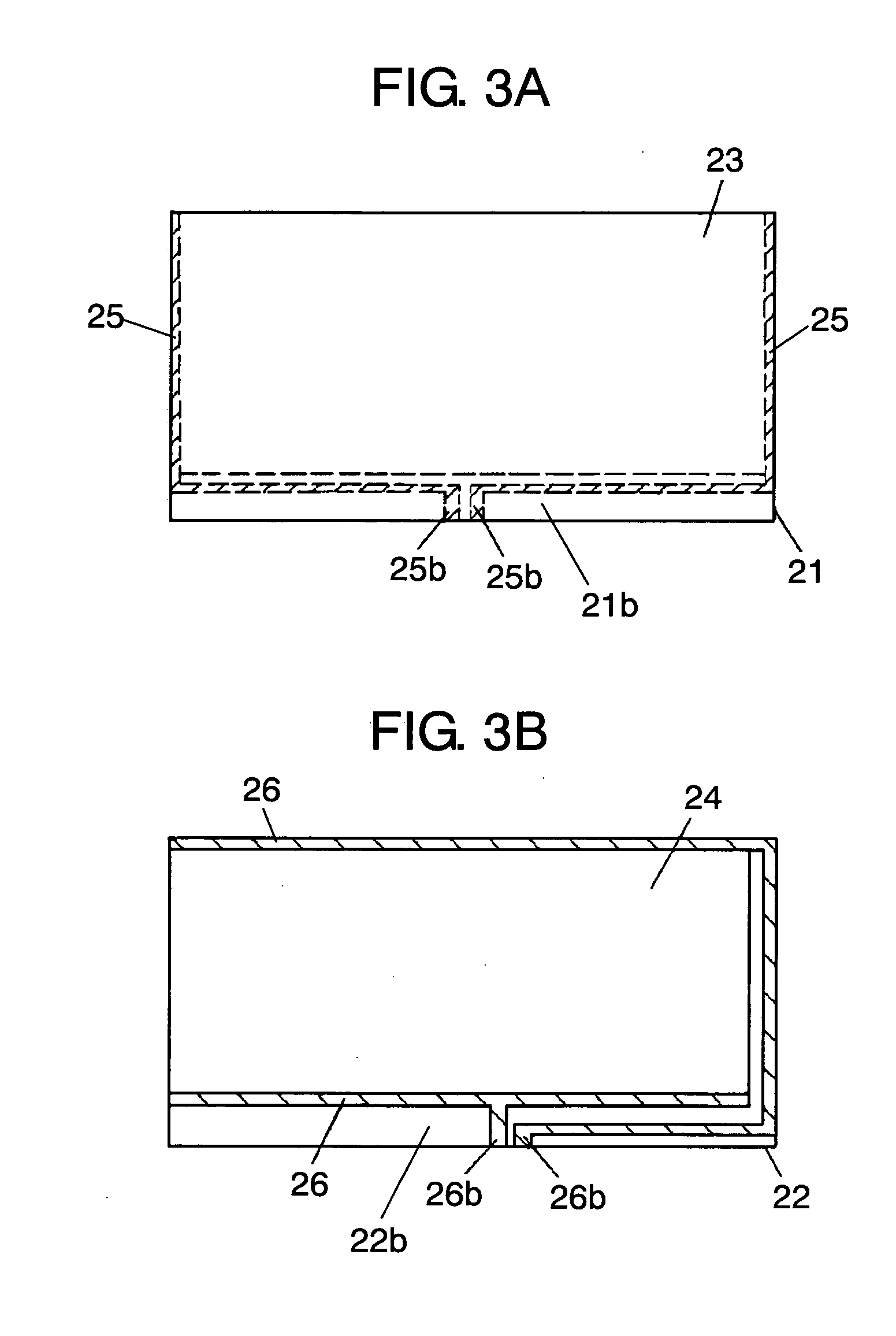
[0035]FIG. 1 is a plan view of a touch panel according to an exemplary embodiment of the present invention. FIG. 2 is a sectional view of a cross section taken along the line 2-2 of the touch panel shown in FIG. 1. FIG. 3A is a plan view of a first substrate used for the touch panel shown in FIG. 1. FIG. 3B is a plan view of a second substrate used for the touch panel shown in FIG. 1. FIG. 4 is a sectional view of a cross section taken along the line 4-4 of the touch panel shown in FIG. 1. FIG. 5 is a cutaway view of a main portion of the touch panel shown in FIG. 1. FIG. 6A is a plan view of a wiring substrate used for the touch panel shown in FIG. 1.

[0036]In FIG. 1 to FIG. 6A, an upper substrate defining first substrate 21 (hereafter referred to as substrate 21) has a film-like form and optical transparency, and it is formed of an opt...


PUM


Abstract

A touch panel includes a first substrate, a second substrate, a wiring substrate provided with a plurality of wiring patterns formed thereon, and an anisotropic conductive adhesive layer. The first substrate has a first conductive layer and first electrodes extending from two opposite sides of the first conductive layer. The second substrate has a second conductive layer confronting the first surface with a space, and second electrodes extending from two opposite sides of the second conductive layer. The anisotropic conductive adhesive layer connects a terminal portion of the wiring patterns to at least one of the first electrodes and the second electrodes. The wiring substrate has a slit or an aperture between the wiring patterns at one end thereof. The touch panel of this structure is easy to produce, and provides reliable operation and electrical connection and separation.

Description


Claims


Application Information

Patent Timeline
Owner PANASONIC CORP
Why Eureka
Try Eureka