Electronic endoscope apparatus

a technology of endoscope and endoscope, which is applied in the field of electronic endoscope apparatus, can solve the problems of reducing and achieve the effect of accurately setting the brightness of the spectroscopic imag

Inactive Publication Date: 2007-08-09
FUJI PHOTO OPTICAL CO LTD
View PDF5 Cites 29 Cited by
  • Summary
  • Abstract
  • Description
  • Claims
  • Application Information

AI Technical Summary

Benefits of technology

[0008] The present invention has been developed in view of the circumstances described above, and it is an object of the present invention to provide an electronic endoscope apparatus for obtaining a spectroscopic image capable of accurately setting the brightness of the spectroscopic image at a desirable level.

Problems solved by technology

Contrary to the expectation, however, it has been found that such control method decreases the brightness of the spectroscopic images.

Method used


Image

  • Electronic endoscope apparatus
  • Electronic endoscope apparatus
  • Electronic endoscope apparatus

Examples


Embodiment Construction

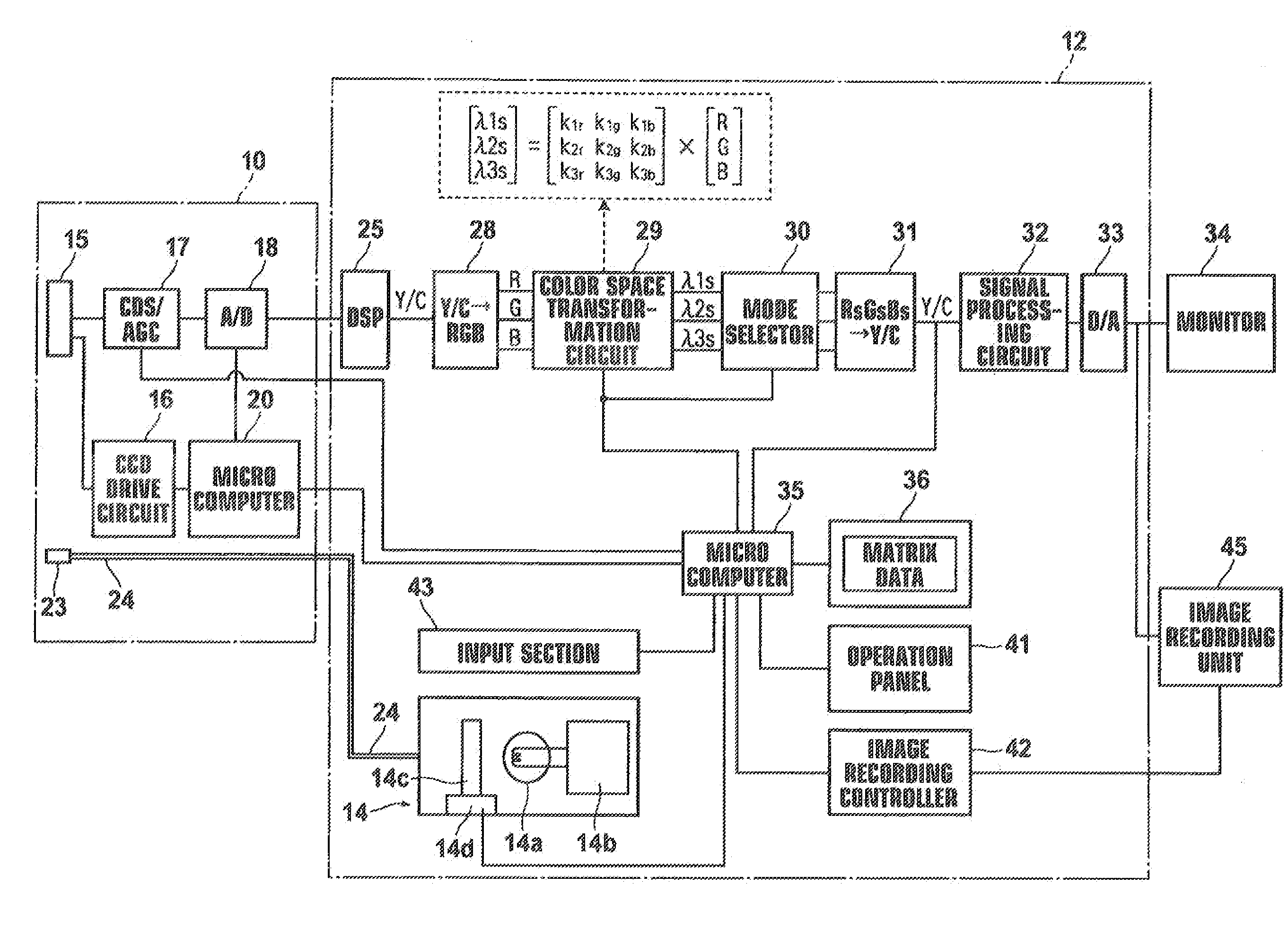
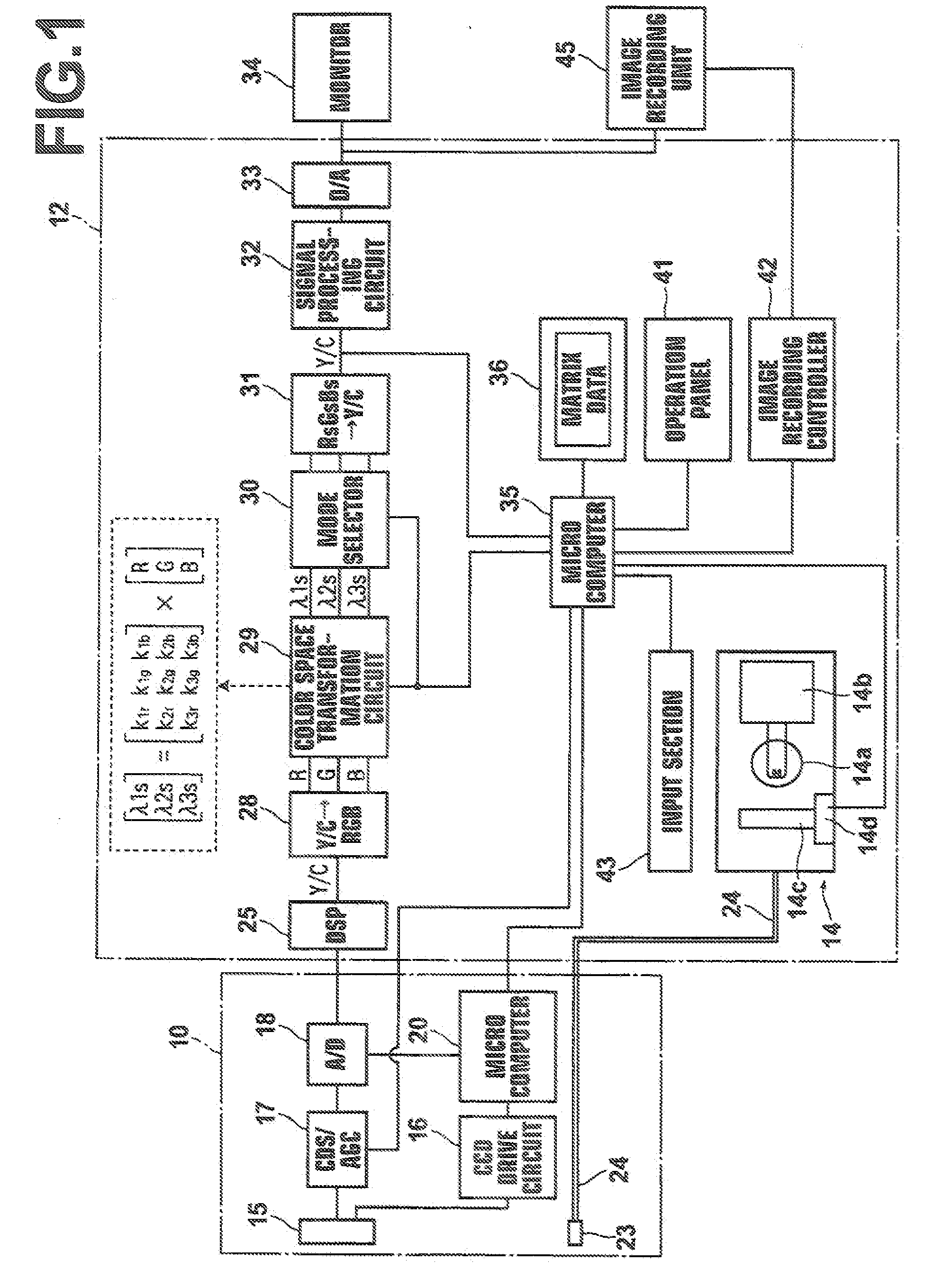
[0038] Hereinafter, exemplary embodiments of the present invention will be described in detail with reference to accompanying drawings. FIG. 1 illustrates a basic construction of the electronic endoscope apparatus according to an embodiment of the present invention. As show in the drawing, the electronic endoscope apparatus includes: a scope 10, i.e., the main body section, and a processor unit 12 to which the scope 10 is detachable attached. The processor unit 12 has therein a light source unit 14 that emits white light. An illumination window 23 is provided at the distal end of the scope 10, and one end of a light guide 24, the other end of which is connected to the light source unit 14, is disposed opposite to the window 23.

[0039] the light source unit 14 includes: a lamp 14a that emits white light; a lamp activation circuit 14b that activates the lamp 14a; an aperture diaphragm 14c disposed on the front side of the lamp 14a; and an aperture diaphragm drive section 14d for openi...


PUM


Abstract

An electronic endoscope apparatus capable of setting the brightness of a displayed spectroscopic image within a desirable range. The apparatus includes: a light source for irradiating white light on an observation target body; a first color conversion imaging the observation target image; a first color conversion circuit for converting Y/C signals to RGB three color image signals; a spectroscopic image generation circuit for generating a spectroscopic image from the RGB three color image signals; a second color conversion circuit for converting the RGB three color image signals to Y/C signals; a light amount regulation means for regulating the amount of white light irradiated on the observation target body; and a light amount control circuit for controlling the light amount regulation means based on the luminance information provided by the Y/C signals outputted from the second color conversion circuit.

Description

BACKGROUND OF THE INVENTION [0001] 1. Field of the Invention [0002] The present invention relates to an electronic endoscope apparatus, and more specifically to an electronic endoscope (picture) within a specific wavelength range by performing arithmetic operation on the image signals representing a color image. [0003] 2. Description of the Related Art [0004] Recently, in the field of electronic endoscope systems with a solid state imaging device, those that performs spectroscopic imaging using combined narrow bandpass filters based on the spectral reflection factors at digestive organs, such as gastric mucosa and the like, i.e., electronic endoscope systems having therein narrow-band filters (Narrow Band Imaging, NBI) have been drawing attention. The system includes three narrow (wavelength) bandpass filters, instead of frame sequential type R (red), G (green), and B (blue) rotation filters. In the system, illumination light beams are sequentially outputted through the narrow bandp...

Claims


Application Information

Patent Timeline
Patent Type & Authority Applications(United States)
IPC IPC(8): B60Q1/124
CPCA61B1/00009A61B5/0084A61B1/045A61B1/043A61B1/000094
Inventor HIGUCHI, MITSURU
Owner FUJI PHOTO OPTICAL CO LTD
Why Eureka
Try Eureka