Thermal sheet and apparatus using the same

a technology of thermal sheets and apparatus, applied in the field of thermal sheets, can solve the problems of temperature deviation between liquid crystal cells, deviation of response speed, brightness deviation in the lcd, etc., and achieve the effect of dissipating heat more efficiently

Inactive Publication Date: 2007-08-09
LG ELECTRONICS INC
View PDF14 Cites 9 Cited by
  • Summary
  • Abstract
  • Description
  • Claims
  • Application Information

AI Technical Summary

Benefits of technology

[0013]An object of the present invention is to provide a thermal sheet to dissipate heat more efficiently.
[0015]Further another object of the present invention is to provide a thermal sheet for dissipating the heat generated in display devices such as LCDs, PDPs, OELDs, or any devices using LEDs, by attaching the thermal sheet to any appropriate surface of the devices.

Problems solved by technology

The heat generated from the CCFL may be transferred unevenly to the liquid crystal panel disposed in front of the backlight unit and cause a temperature deviation among the liquid crystal cells.
Such temperature deviation of the liquid crystal cells may cause a deviation of the response speed of the liquid crystal cells, which may cause a brightness deviation in the LCD.
However, activating some of the discharging cells for light emission will also generate heat, which raises the temperature of the PDP as a whole.
However, the heat transferred to the glass substrates cannot be easily conducted in a parallel direction of the surface of the panel mainly due to the poor thermal conductivity of glass material of the substrates.
Such a temperature deviation of the panel may deteriorate the performance of the discharging cells.
In addition, the above-noted heat related problems may also occur in other display devices such as the display device using light emitting diodes (LED) and the organic electroluminescent device (OELD).
Theses heat related problems may deteriorate the life-cycle and display quality of the devices.
However, the conventional thermal sheet is not efficient to dissipate the heat.

Method used


Image

  • Thermal sheet and apparatus using the same
  • Thermal sheet and apparatus using the same
  • Thermal sheet and apparatus using the same

Examples


Embodiment Construction

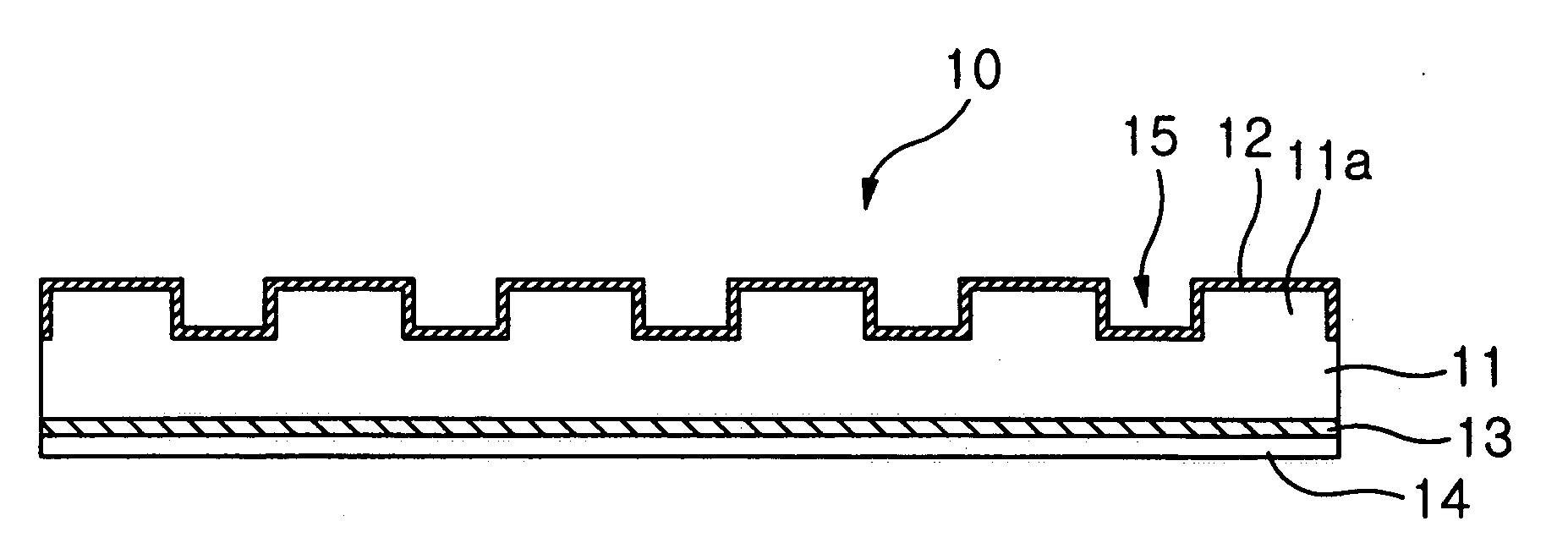
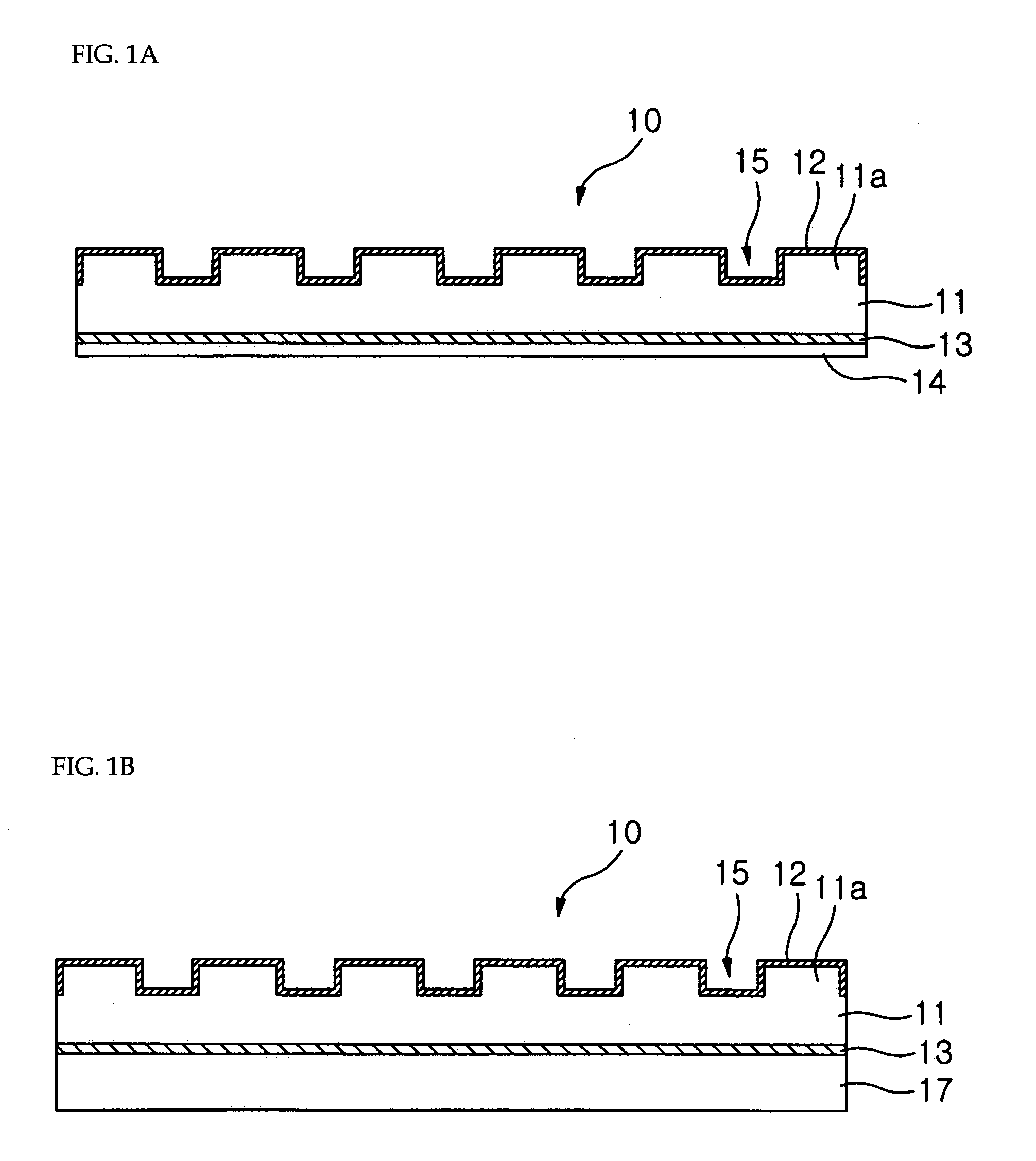
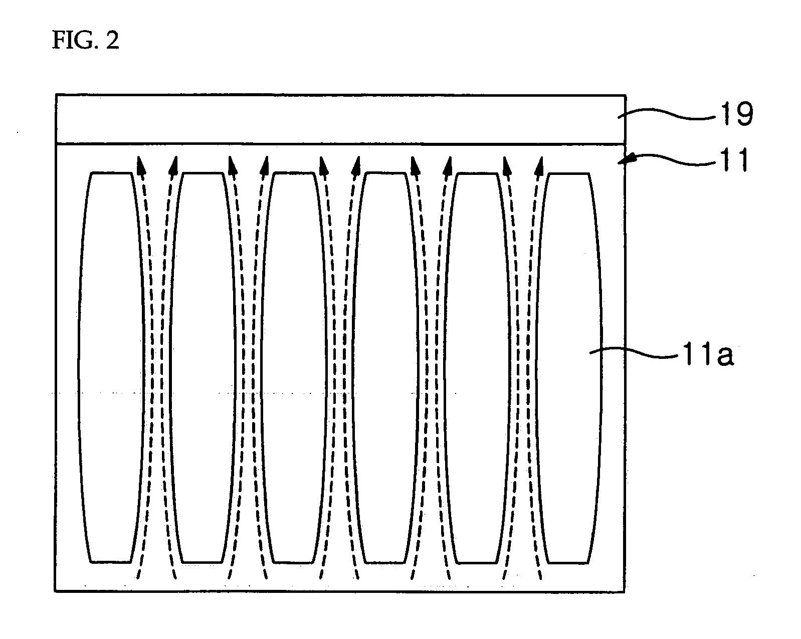
[0024]FIG. 1A is a cross-sectional view of a thermal sheet of an embodiment of the present invention, FIG. 1B is a cross-sectional view of the thermal sheet of FIG. 1A attached to a heat-generating device in accordance with an embodiment of the present invention and FIG. 2 is a plane view of the base film of FIG. 1A and a heat sink connected to the base film in accordance with an embodiment of the present invention.

[0025]Referring to FIGS. 1A-B and FIG. 2, a thermal sheet 10 according to an embodiment of the present invention comprises a base film 11. The base film 11 has a first surface provided with protrusions 11a which are arranged in a first direction at a predetermined interval and grooves 15 between two adjacent protrusions 11a. The opposite surface to the first surface of the base film 11 in the illustrated embodiment is substantially flat. However, the opposite surface can be configured to other shapes to accommodate the shape of the heat-generating device 17 attached there...


PUM

PropertyMeasurementUnit
temperatureaaaaaaaaaa
thermalaaaaaaaaaa
thermally conductingaaaaaaaaaa

Abstract

A thermal sheet and an apparatus using the same are provided. The thermal sheet, as embodied, includes a base film including: a plurality of protrusions at a first surface of the base film and extending along a first direction, and a plurality of grooves between two adjacent protrusions as a heat flow path along the first direction; and a thermal layer for thermally conducting and / or radiating heat transferred from the base film, the thermal layer being disposed on the first surface of the base film.

Description

CROSS-REFERENCE TO RELATED APPLICATIONS[0001]This Nonprovisional application claims priority under 35 U.S.C. §119(a) on Patent Application No. 10-2006-0012197 filed in Korea on Feb. 8, 2006, the entire contents of which are hereby incorporated by reference.BACKGROUND OF THE INVENTION[0002]1. Field of the Invention[0003]The present invention relates to a thermal sheet, particularly relates to a thermal sheet as a heat transfer medium of a display device, such as a liquid crystal display device, a plasma display panel, an organic electroluminescent device, a display using light emitting diodes and the like. The thermal sheet of the present invention may be simply attached to any appropriate area of a heat-generating device.[0004]2. Description of the Related Art[0005]The liquid crystal display device (LCD) is an electronic device which converts electrical information to image information by changing the light transmittance of liquid crystals therein and thereby displays the image info...

Claims


Application Information

Patent Timeline
Patent Type & Authority Applications(United States)
IPC IPC(8): B32B33/00B32B3/00
CPCB32B7/06Y10T428/24612B32B15/20H05K7/20963B32B5/16B32B15/16B32B27/14B32B3/30B32B2260/025B32B2260/046B32B2264/105B32B2264/108B32B2307/302B32B2457/20Y10T428/14B32B7/12B65B3/26B65B3/06
Inventor JEONG, SEOK HWA
Owner LG ELECTRONICS INC
Why Eureka
Try Eureka