
Solar blackbody waveguide for solar assisted oil recovery applications

Active Publication Date: 2007-08-16
MECHAM TRAVIS W +1
View PDF12 Cites 17 Cited by
  • Summary
  • Abstract
  • Description
  • Claims
  • Application Information

AI Technical Summary

Benefits of technology

[0016] The present invention is a method to enhance oil shale, oil sand, asphaltic crude oil, or other high viscosity crude oil production by using concentrated energy in the form of solar flux

Problems solved by technology

However, the term “oil shale” is not an accurate description for these potential energy resources.
These shale formations are often located too shallow in the earth to have been subjected to sufficient temperatures to complete the process of transformation into the liquid oil form.
Traditional retorting techniques present several problems and limitations.
The costs associated with the mining processes and the inefficiencies of the retorting equipment limit the economic viability of traditional retorting processes.
Also, post-retort residual rock fines and other tailings from the mining process have a significant adverse environmental impact.
This increase in volume results in an inability to return all of the residual materials to landfill in the mines from which they originated.
In-situ heating techniques also present several problems and limitations.
Unfortunately, a large amount of electrical energy or gas is needed to heat and to maintain the formation at a sufficient temperature.
In addition to the fuel costs, the remote location of these types of oil producing fields necessitates construction of pipelines or electrical transmission infrastructure to bring sufficient gas or electricity to these sites.
Without relatively high oil prices to support the additional operation and capital construction costs, these extraction techniques can be cost prohibitive.
This process has similar limitations to the oil-shale mining techniques discussed above.
Specifically those limitations involve the mining and heating costs which limit the economic viability of the process.
These in-situ techniques are economically limited due to the cost of energy to create steam and the need for large quantities of water.

Method used


Image

  • Solar blackbody waveguide for solar assisted oil recovery applications
  • Solar blackbody waveguide for solar assisted oil recovery applications
  • Solar blackbody waveguide for solar assisted oil recovery applications

Examples


Embodiment Construction

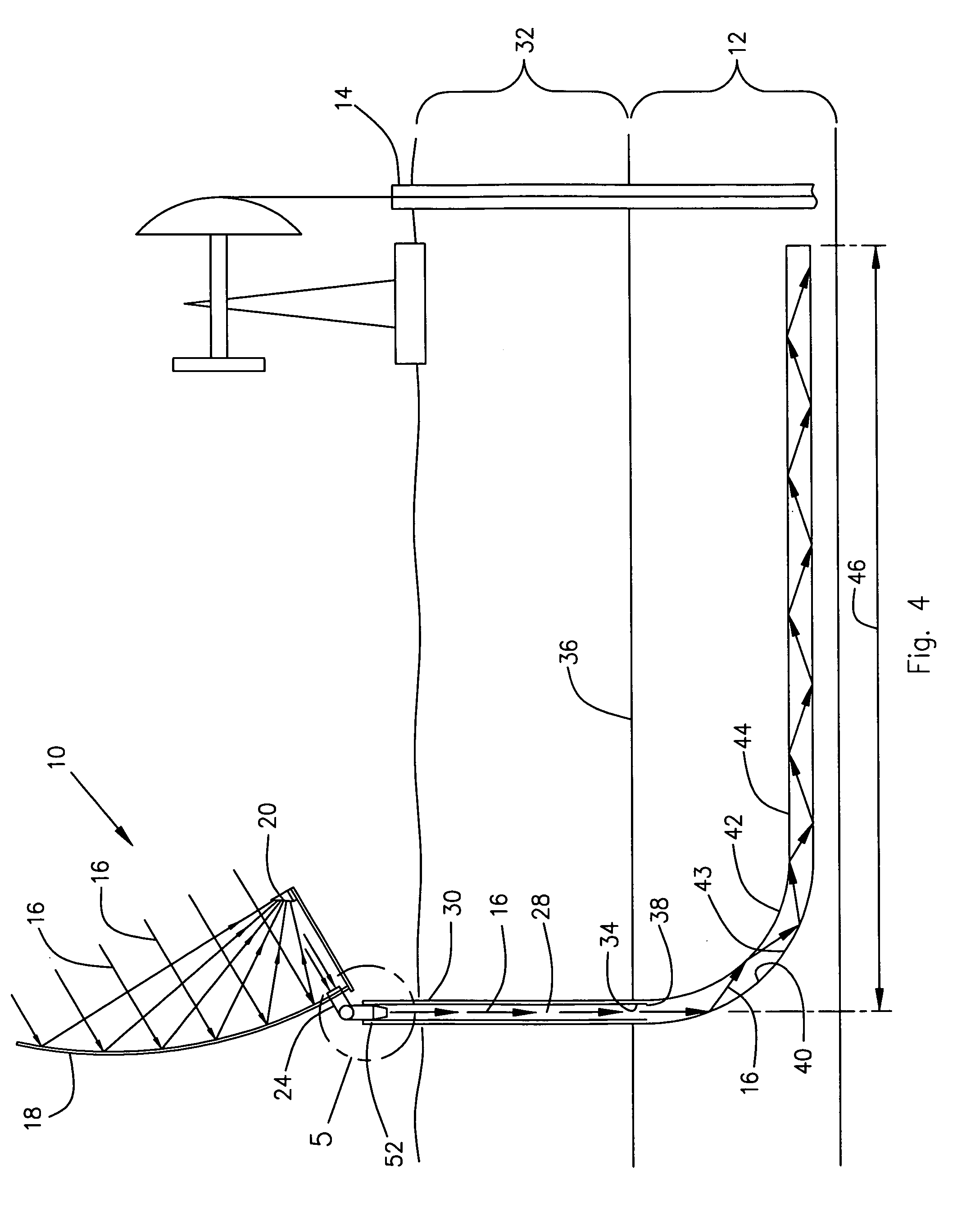
[0027] Referring now to the drawings and initially to FIG. 4, there is shown a solar blackbody waveguide 10 installed in an ore-bearing or oil-bearing formation 12 in association with a crude oil producing well 14 located in that same formation 12. This illustration shows a method to enhance oil shale, oil sand, asphaltic crude oil, or other high viscosity crude oil production in a formation 12 by using concentrated energy in the form of light, light rays, solar energy, or solar flux 16 to provide the energy to heat the formations 12 in situ. The method uses a solar blackbody waveguide 10 which acts as a solar-powered heating element to direct heat to the oil bearing formation 12.

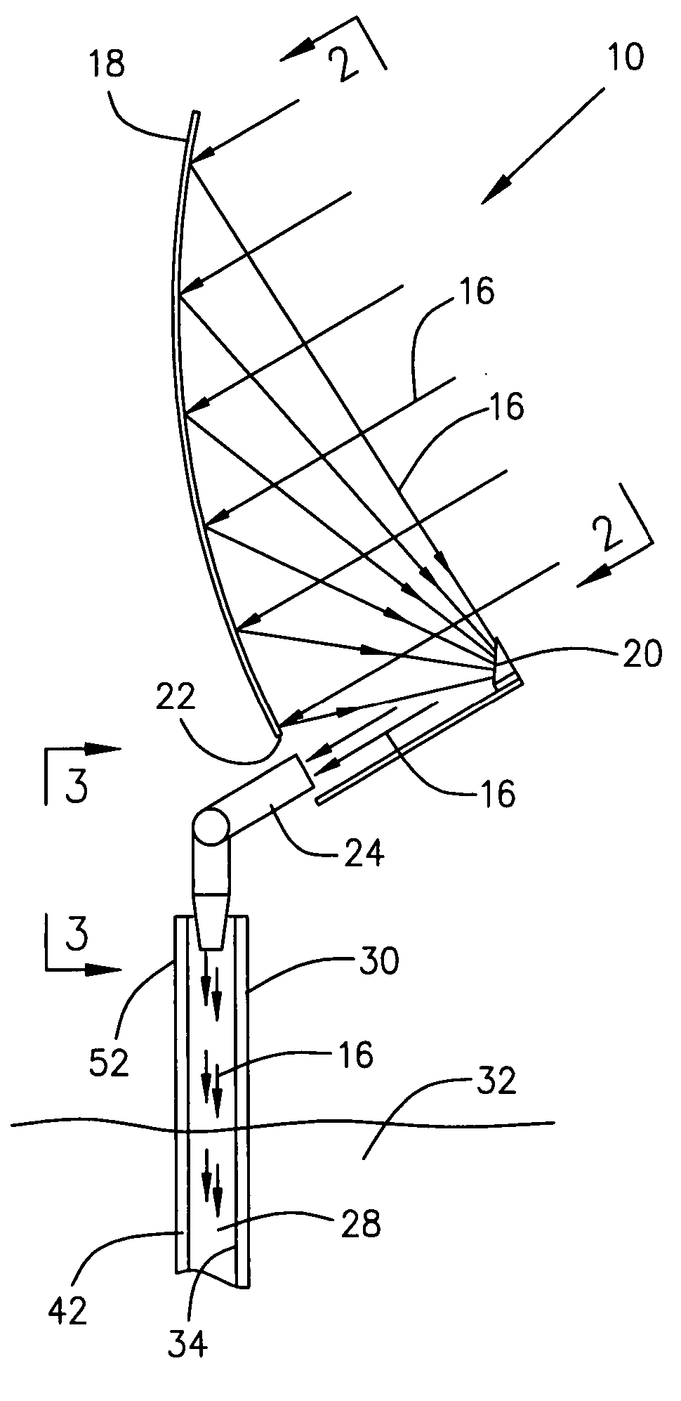
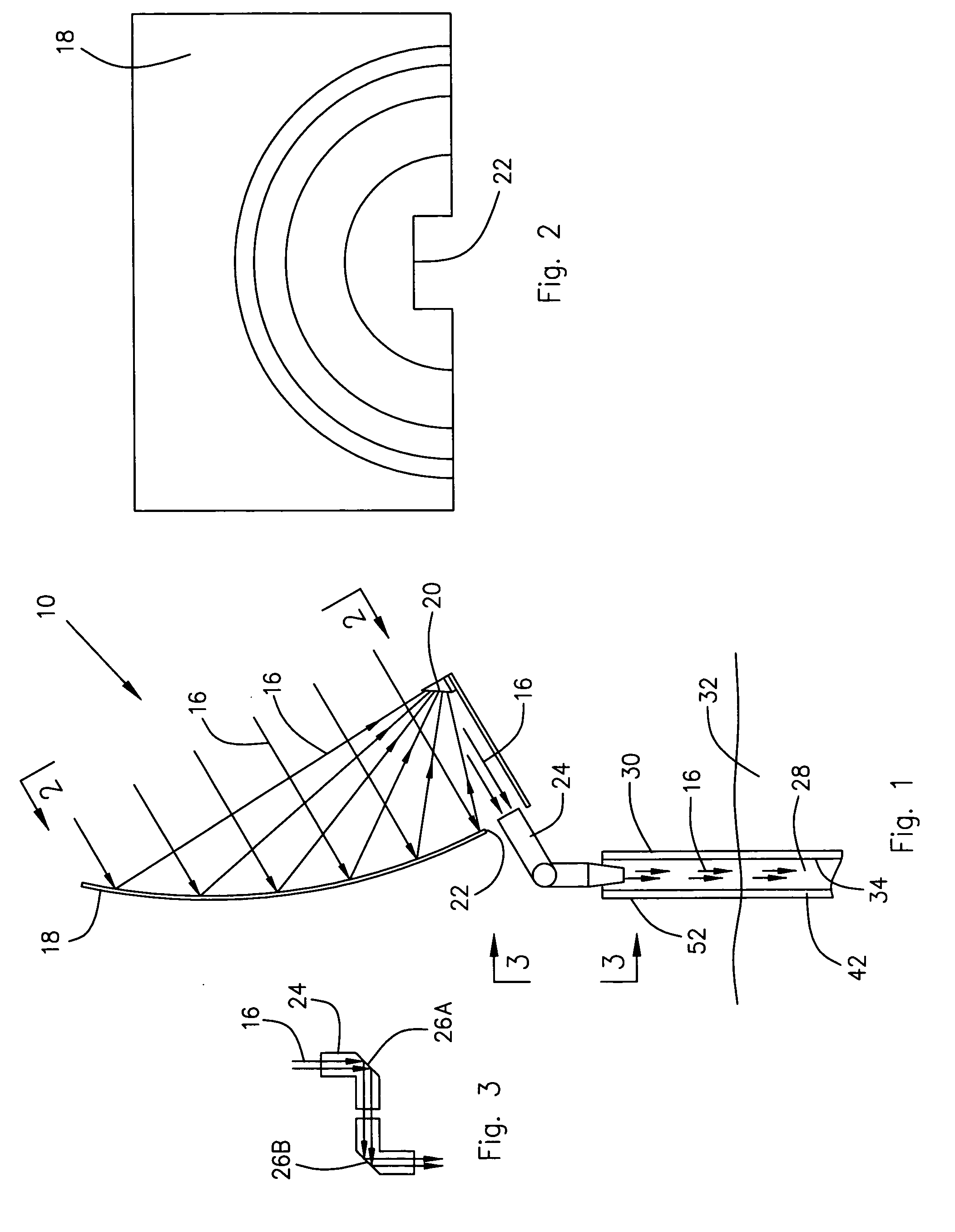
[0028] Referring now also to FIGS. 1 and 2, the solar blackbody waveguide 10 is provided with one or more parabolic mirrors 18 which are used to concentrate solar energy 16 radiating from the sun (not illustrated). For ease of illustration, only one parabolic mirror 18 is illustrated in the drawings.

[0029...


PUM


Abstract

A method to enhance oil shale, oil sand, asphaltic crude oil, or other high viscosity crude oil production by using a solar blackbody waveguide to heat these formations in situ. A parabolic mirror collects and directs the solar flux into a vertical shaft of a well drilled into the formation. This vertical shaft is lined with a reflective sleeve that reflects nearly all of the sunlight down into the well bore. The reflective sleeve ends at the top of the formation so that below this point, the solar flux is permitted to make successive reflections with the interior of the metal well casing or solar blackbody waveguide coil. The coil absorbs the solar flux, converting it to heat. Heat from the coil is transferred by conduction into the formation and allowing the formation to be produced by traditional methods.

Description

BACKGROUND OF THE INVENTION [0001] 1. Field of the Invention [0002] The present invention relates to a method for enhancing in-situ oil production from oil shale, oil sand, asphaltic crude oil, or other high viscosity crude oil formations. This method employs delivering energy in the form of concentrated solar flux to these formations in order to passively heat them and thereby increase their oil production. [0003] 2. Description of the Related Art [0004] The heating of oil shale formations has been demonstrated in the prior art as the critical component of the in-situ production of oil from oil shale. Heating of the formation has also been shown in the prior art to enhance production yields from certain oil-bearing zones containing viscous crude oils such as oil sand formations and asphaltic crude fields. [0005] Approximately two trillion (2,000,000,000,000) barrels of potentially recoverable oil shale resources are located in the eastern and western states of the United States. Th...

Claims


Application Information

Patent Timeline
IPC IPC(8): E21B43/24F24S90/00F24S23/70F24S23/71F24S50/20
CPCE21B43/24F24J2/067Y02E10/42F24J2/18F24J2/12F24S23/12F24S23/71F24S23/79Y02E10/40
Inventor MECHAM, TRAVIS W.ASHTON, LESLIE CLARK
Owner MECHAM TRAVIS W
Learn More