Running and cementing tubing

Inactive Publication Date: 2007-08-16
ANDERGAUGE
View PDF25 Cites 78 Cited by
  • Summary
  • Abstract
  • Description
  • Claims
  • Application Information

AI Technical Summary

Benefits of technology

[0007] According to a first aspect of the present invention there is provided a method of running a bore-lining tubing string into a bore, the

Problems solved by technology

The outer diameter of the strings will be only slightly less than the bore inner diameter and thus, particularly in extended reach and highly deviated bores, there may be considerable friction between the string and the bore tending to resist movement of the string through the bore.
However, it may prove difficult to apply torque from surface to rotate such a shoe, as the connec

Method used


Image

  • Running and cementing tubing
  • Running and cementing tubing
  • Running and cementing tubing

Examples


Example

DETAILED DESCRIPTION OF THE DRAWINGS

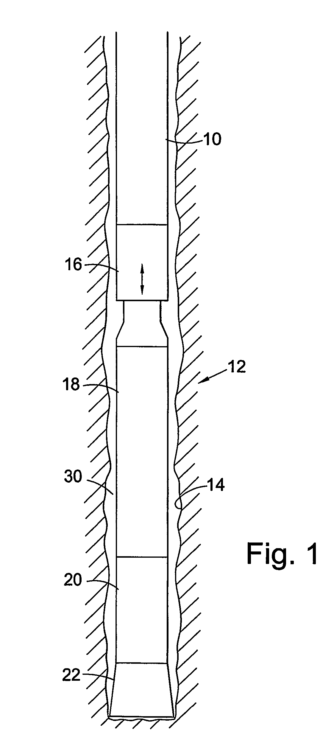
[0027] Reference is first made to FIG. 1 of the drawings, which illustrates the leading end of a string of bore-lining tubing 10 incorporating apparatus 12 in accordance with an embodiment of the present invention. In particular, the tubing is in the form of liner 10 intended to form the last lined section of a drilled bore 14 which has been drilled from surface to intersect a hydrocarbon-bearing formation. In this embodiment the liner has a solid wall, but other embodiments of the invention may involve use of slotted or otherwise perforated tubing.

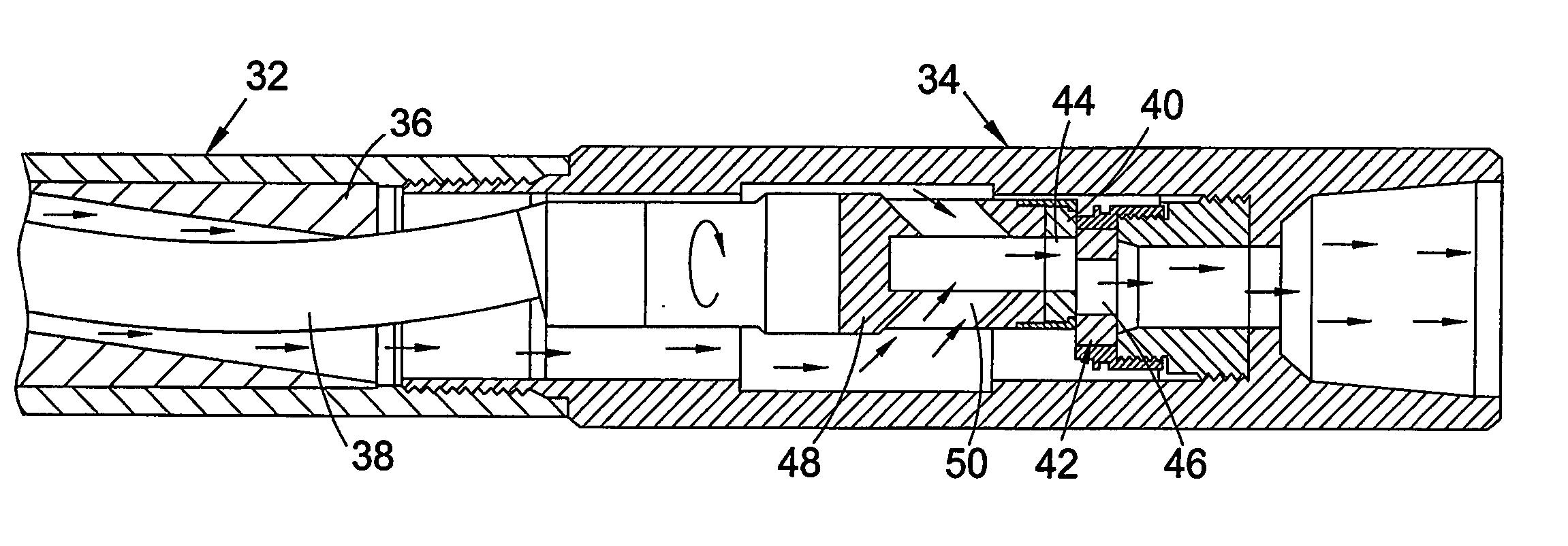
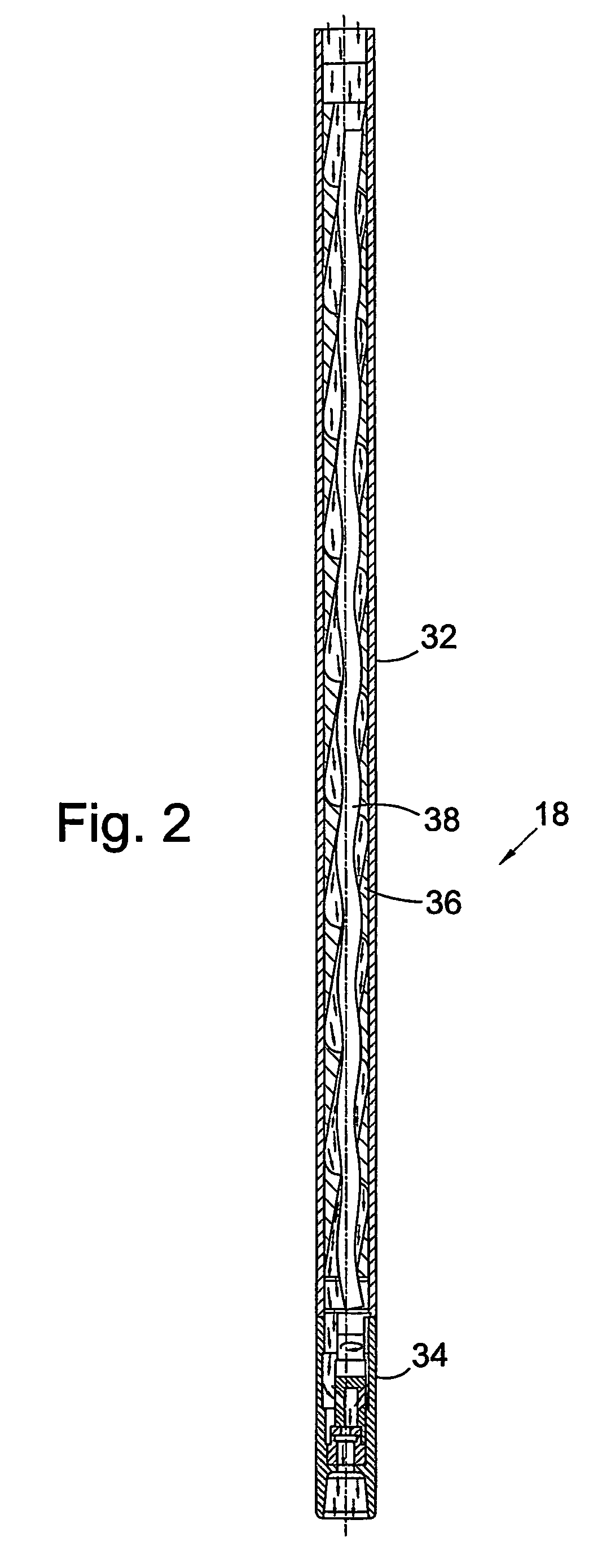
[0028] The apparatus 12 comprises a shock sub 16, an agitator 18, a downhole motor 20 and a drill bit 22 and, as will be described, is used to facilitate running the liner string 10 into the bore 14 and then cementing the liner string 10 in the bore.

[0029] The drill bit 22 and downhole motor 20 are substantially conventional and are used in this embodiment to clear obstructions from the bore 14 as th...


PUM


Abstract

A method of running a bore-lining tubing string into a bore includes running a tubing string, typically a liner string, into a bore while agitating the string. The agitation of the string reduces the friction between the string and the bore wall and thus facilitates the translation of the string into the bore. The agitation may also take place while the tubing is being cemented in the bore. Pressure pulses may be applied to fluid in the bore, which fluid may be cement slurry.

Description

FIELD OF THE INVENTION [0001] This invention relates to apparatus and methods for use in running tubing strings into drilled bores. Aspects of the invention also relate to cementing tubing in drilled bores. BACKGROUND OF THE INVENTION [0002] Bores drilled to access subterranean formations, and in particular hydrocarbon-bearing formations, are typically lined with metallic tubing, known as casing or liner. After the tubing is run into the bore, the annulus between the tubing and the surrounding bore wall is filled with cement slurry which sets to seal the annulus to prevent, for example, flow of fluid through the annulus from a high pressure formation intersected by the bore into a lower pressure formation intersected by another portion of the bore. [0003] Casing and liner tend to be run into bores as strings of conjoined tubing sections, which strings may be up to several thousand metres long. The outer diameter of the strings will be only slightly less than the bore inner diameter ...

Claims


Application Information

Patent Timeline
IPC IPC(8): E21B28/00E21B31/00E21B31/113
CPCE21B31/113E21B31/005E21B28/00
Inventor EDDISON, ALAN MARTYNROBERTSON, LESLIEINNES, RICHARD ALEXANDER
Owner ANDERGAUGE
Why Eureka
Try Eureka