Energy management beam

Inactive Publication Date: 2007-08-16
SHAPE CORP
View PDF99 Cites 15 Cited by
  • Summary
  • Abstract
  • Description
  • Claims
  • Application Information

AI Technical Summary

Benefits of technology

[0012] An aspect of the present invention is to provide an energy management tube adapted to reliably and predictably absorb substantial impact energy when impacted longitudinally. The energy management tube comprises an outer first tube section and an inner second tube section, with the inner second tube section being at least partially located within the outer first tube section, and with the outer first tube section having a stepped outer surface. The energy management tube also comprises at least one spanning section connecting a first outer end of the outer first tube s

Problems solved by technology

However, this process generates raw material scrap.
Also, the welding process is a secondary operation that adds to manufacturing overhead costs.
Further, the welded crush towers are subject to significant product variation and significant variation in product impact strength, force-versus-deflection curves, energy absorption curves, and crush failure points.
However, as the strength of a crush tower is increased, there is a tendency to transmit higher and higher loads from the bumper beam directly into the vehicle frame.
This is often not desirable.
In particular, crush towers that are very high in strength will tend to transmit undesirably high load spikes from the bumper beam to the vehicle frame.
This is often followed by a cat

Method used


Image

  • Energy management beam
  • Energy management beam
  • Energy management beam

Examples


Embodiment Construction

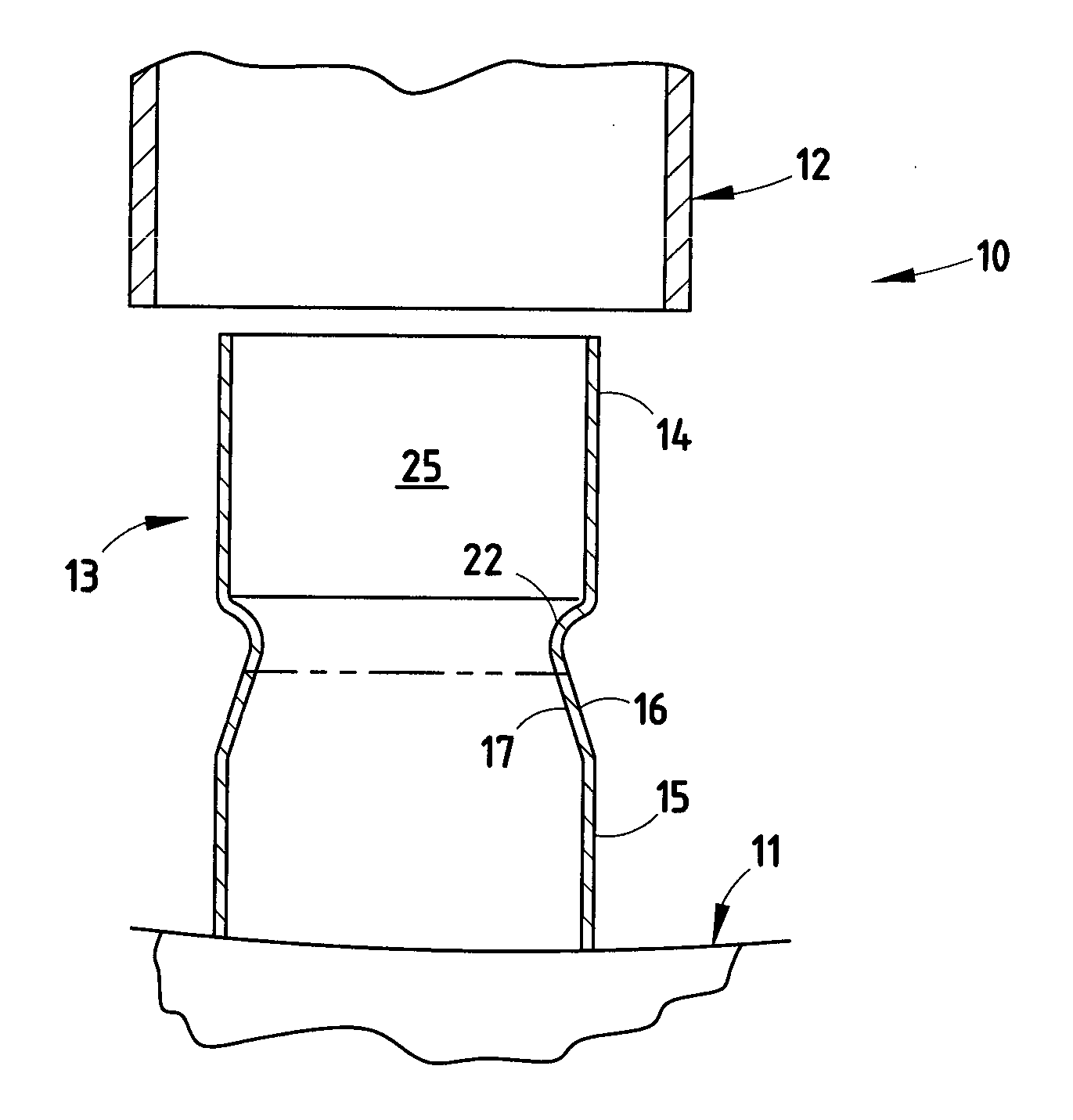
[0075] For purposes of description herein, the terms “upper,”“lower,”“right,”“left,”“rear,”“front,”“vertical,”“horizontal,” and derivatives thereof shall relate to the invention as orientated in FIG. 1. However, it is to be understood that the invention may assume various alternative orientations, except where expressly specified to the contrary. It is also to be understood that the specific devices and processes illustrated in the attached drawings, and described in the following specification are simply exemplary embodiments of the inventive concepts defined in the appended claims. Hence, specific dimensions and other physical characteristics relating to the embodiments disclosed herein are not to be considered as limiting, unless the claims expressly state otherwise.

[0076] It is noted that the present invention can include utilizing the energy management technology (EMT) in thermoplastic and thermoset polymeric materials, with and without filler and reinforcement materials such ...


PUM


Abstract

A tube comprising an outer tube section with a stepped outer surface and an inner tube section, with the inner tube section being located within the outer tube section. The tube also comprises a spanning section connecting an end of the outer tube section to an end of the inner tube section. The outer tube section is longer than the inner tube section, whereby, upon undergoing a longitudinal impact, the outer tube section crushes predictably and sooner than the inner tube section upon the energy management tube receiving forces from the longitudinal impact, to thereby create a first energy absorption level during crushing of the outer tube section alone and a second energy absorption level during crushing of the outer tube section and the inner tube section.

Description

CROSS-REFERENCE TO RELATED APPLICATIONS [0001] This application claims the benefit of U.S. Provisional Application No. 60 / 607,677 entitled PLASTIC ENERGY MANAGEMENT BEAM, which was filed Sep. 7, 2004, the entire contents of which are hereby incorporated herein by reference. This application also claims the benefit of U.S. Provisional Application No. 60 / 751,522 entitled ENERGY MANAGEMENT SYSTEM, which was filed Dec. 19, 2005, and U.S. Provisional Application No. 60 / 793,069 entitled ENERGY MANAGEMENT SYSTEM, which was filed Apr. 19, 2006, the entire contents of both of which are hereby incorporated herein by reference. [0002] This application is a continuation-in-part of U.S. application Ser. No. 11 / 220,881, filed Sep. 7, 2005 and entitled PLASTIC ENERGY MANAGEMENT BEAM, which is a continuation-in-part of U.S. application Ser. No. 10 / 997,332, filed Nov. 24, 2004 and entitled TUBULAR ENERGY MANAGEMENT SYSTEM FOR ABSORBING IMPACT ENERGY, which is a continuation of U.S. application Ser. ...

Claims


Application Information

Patent Timeline
IPC IPC(8): B60R19/34
CPCB60R19/18B60R19/34B60R2021/0293B60R2019/1866B60R2019/1893B60R21/045
Inventor EVANS, DARIN
Owner SHAPE CORP
Why Eureka
Try Eureka