Dynamic boundary mapping using position-determination systems

a position-determination system and dynamic boundary mapping technology, applied in the field of asset tracking, can solve the problems of difficult to be accurate in taking measurements, easy to make measurement or drawing errors, labor-intensive approaches, etc., and achieve the effect of greater accuracy

Inactive Publication Date: 2007-08-16
IBM CORP
View PDF14 Cites 67 Cited by
  • Summary
  • Abstract
  • Description
  • Claims
  • Application Information

AI Technical Summary

Benefits of technology

[0010] The invention provides an approach for automatic and dynamic mapping of zone boundaries for position-determination systems. The system of the present invention utilizes beacons (“position determining devices”) to identify the boundaries and limits of device area coverage (“zone”) for tracking objects with a position-determination system. Beacons, used both to identify zone boundaries and to tag assets to be tracked, are distributed within the zone. The beacon locations are then detected and displayed in the visualization application. Three or more beacons may be link

Problems solved by technology

While these capabilities exist, defining the zones in location aware systems is a time consuming manual process, and thus often error-prone,
Both these approaches are labor-intensive.
It is especially difficult to be accurate in taking the measurements when the zones are in open areas

Method used


Image

  • Dynamic boundary mapping using position-determination systems
  • Dynamic boundary mapping using position-determination systems
  • Dynamic boundary mapping using position-determination systems

Examples


Embodiment Construction

[0015] While various embodiments of the present invention are discussed in detail below, it should be appreciated that the present invention provides inventive concepts that may be embodied in a wide variety of specific contexts. The specific embodiments discussed are merely illustrative of specific ways to make and use the invention, and do not limit the scope of the invention. In other instances, well-known features have not been described in detail so as not to obscure the invention.

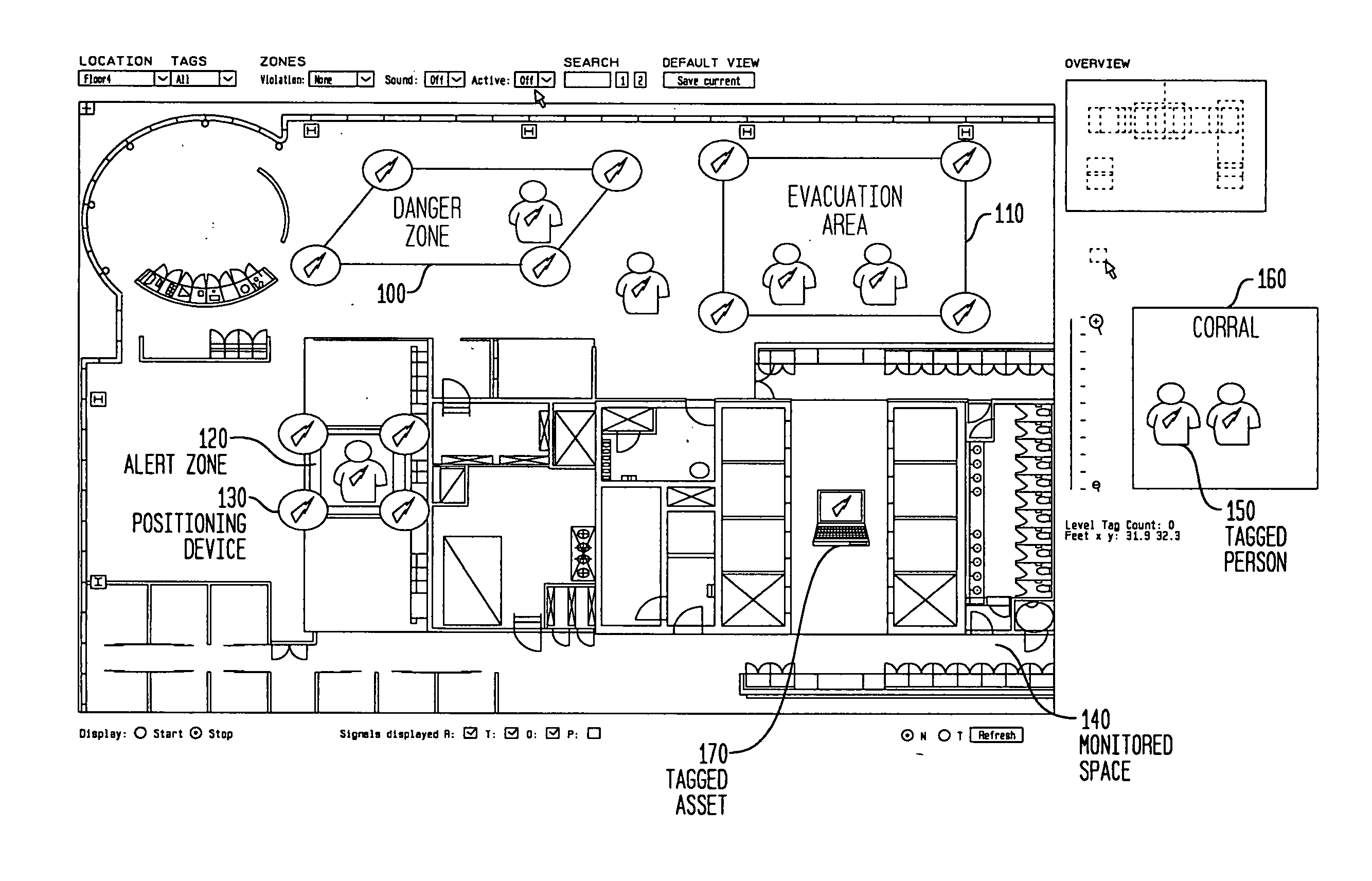
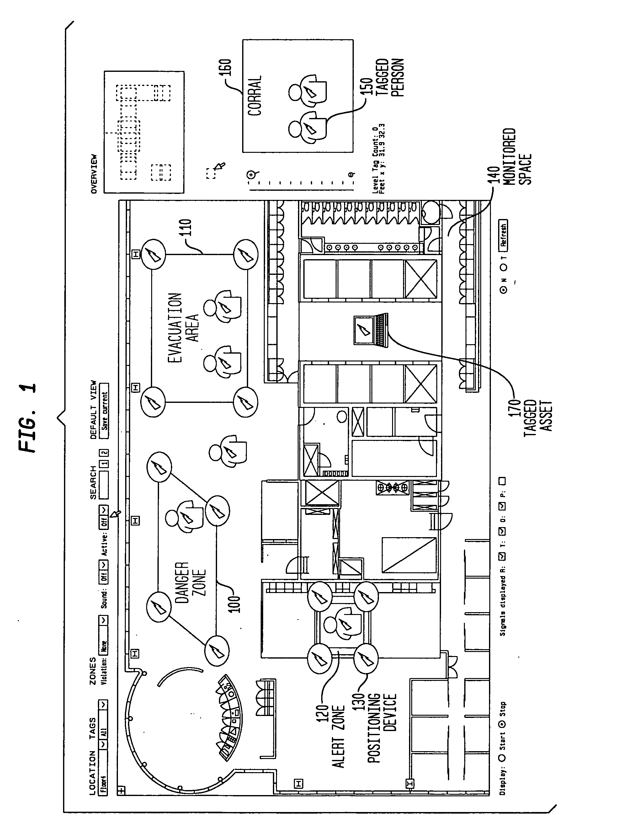
[0016] Referring first to FIG. 1, there is shown a block diagram illustrating defined zones for use in a location aware system of at least one embodiment of the present invention. In the present invention, zones may be dynamic or static. FIG. 1 illustrates a user interface for a location aware asset monitoring computer application for use with at least one embodiment of the present invention. While the interface of FIG. 1 represents a computer graphic user interface, any type of display device may be...


PUM


Abstract

The invention provides an approach for automatic and dynamic mapping of zone boundaries for position-determination systems. The system of the present invention utilizes beacons (“position determining devices”) to identify the boundaries and limits of device area coverage (“zone”) for tracking objects with a position-determination system. Beacons, used both to identify zone boundaries and to tag assets to be tracked, are distributed within the zone. The beacon locations are then detected and displayed in the visualization application. Three or more beacons may be linked together, either manually or automatically, to establish a detection zone. Using beacons to establish detection zone boundaries eliminates guesswork and its associated errors, and produces a zone boundary that is actually valid. In an improvement over present systems, greater accuracy is assured using zone-defining beacons, because if a beacon is unintentionally placed in an area unavailable to the position-determination system, that beacon will not appear in the visualization application display, and thus will not be available to create an incorrect zone representation.

Description

FIELD OF THE INVENTION [0001] The invention disclosed broadly relates to the field of asset tracking, and more particularly relates to the field of dynamic mapping of boundaries in a position-determination system. BACKGROUND OF THE INVENTION [0002] Computer systems are becoming valuable tools in the management and tracking of assets, particularly the ability to locate assets with a defined area. “Location-aware” applications, which are enabled by position-determination systems, can track employees, vehicles, or other objects within a defined space. These location aware systems are becoming more common both within business enterprises and, to some extent, among individual consumers as well. [0003] Location aware systems may track the location of persons or assets using a variety of methods and devices. For example, active or passive Radio Frequency Identification (RFID) tags, Ultra Wideband tags, Wireless Fidelity (Wi-Fi) beacons, and Global Positioning System (GPS)-enabled mobile ph...

Claims


Application Information

Patent Timeline
IPC IPC(8): G08B1/08G08B13/14
CPCG06Q10/08G07C9/00103G08B13/2462G08B13/14G08B13/2417G07C9/00111G07C9/27G07C9/28
Inventor COLE, ALAN G.ELLIOTT, JEFFREY G.MAIER, HOLGER H.MOSKOWITZ, PAUL A.PODVRATNIK, AMADEUS
Owner IBM CORP
Why Eureka
Try Eureka