Video encoding/decoding method and apparatus

a video and encoding technology, applied in the field of video encoding/decoding methods and apparatuses, can solve the problems of reducing the encoding efficiency, not always an effective method in terms of robust quantization, and human comparatively insensitive to high frequency regions

Inactive Publication Date: 2007-08-16
KK TOSHIBA
View PDF11 Cites 150 Cited by
  • Summary
  • Abstract
  • Description
  • Claims
  • Application Information

AI Technical Summary

Problems solved by technology

However, this conventional method needs to prepare an allocation table according to coarseness of quantization.
Therefore, it is not always an effective method in terms of robust quantization.
However, the human is comparatively insensitive on the high frequency region according to human visual property.
A method for transmitting a quantization matrix of H.264 high profile may increase an overhead for encoding the quantization matrix and thus largely decrease the encoding efficiency, in an application used at a low bit rate such as cellular phone or mobile device.
However, it is impossible to change the characteristic.
Further, when a degree of change of the quantization matrix is transmitted, degrees of freedom for changing the quantization matrix are largely limited.
There is a problem that these results make it difficult to utilize the quantization matrix effectively.

Method used


Image

  • Video encoding/decoding method and apparatus
  • Video encoding/decoding method and apparatus
  • Video encoding/decoding method and apparatus

Examples


first embodiment

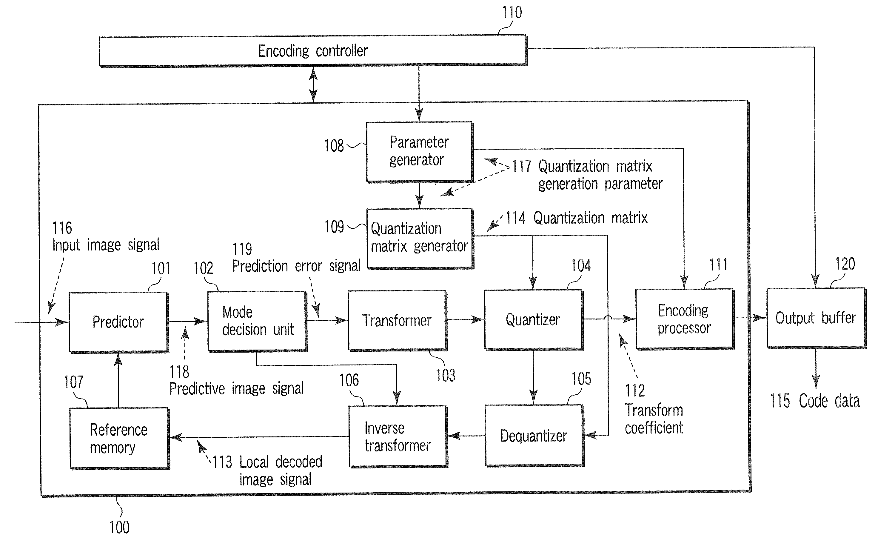
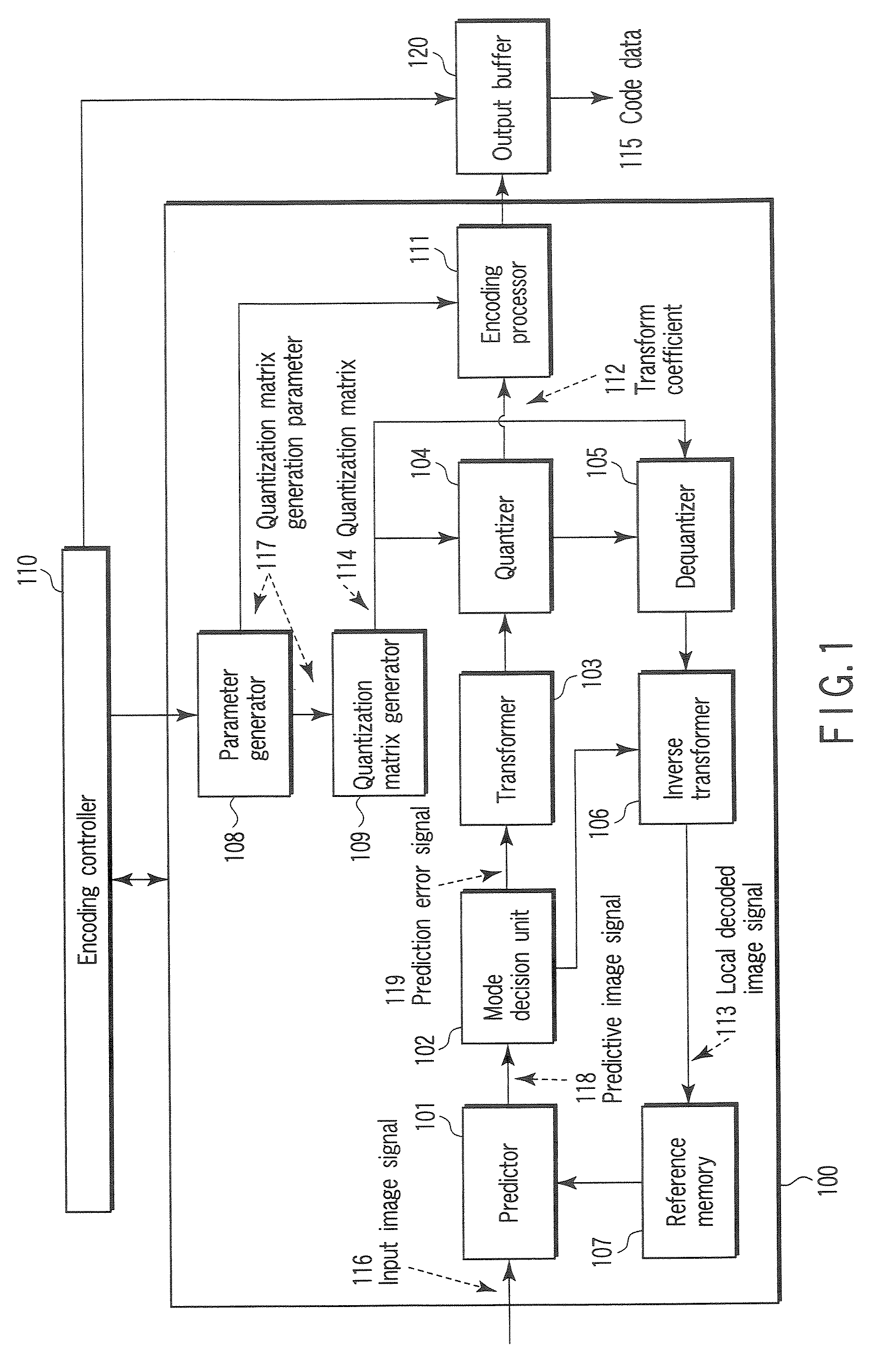
[0036]According to the first embodiment shown in FIG. 1, a video signal is divided into a plurality of pixel blocks and input to a video encoding apparatus 100 as an input image signal 116. The video encoding apparatus 100 has, as modes executed by a predictor 101, a plurality of prediction modes different in block size or in predictive signal generation method. In the present embodiment it is assumed that encoding is done from the upper left of the frame to the lower-right thereof as shown in FIG. 4A.

[0037]The input image signal 116 input to the video encoding apparatus 100 is divided into a plurality of blocks each containing 16×16 pixels as shown in FIG. 4B. A part of the input image signal 116 is input to the predictor 101 and encoded by an encoder 111 through a mode decision unit 102, a transformer 103 and a quantizer 104. This encoded image signal is stored in an output buffer 120 and then is output as coded data 115 in the output timing controlled by an encoding controller 11...

second embodiment

[0092]Multipath encoding concerning the second embodiment is explained referring to a flow chart of FIG. 12. In this embodiment, the detail description of the encoding flow having the same function as the first embodiment of FIG. 3, that is, steps S002-S015, is omitted. When the optimal quantization matrix is set every picture, the quantization matrix must be optimized. For this reason, multipath encoding is effective. According to this multipath encoding, the quantization matrix generation parameter can be effectively selected.

[0093]In this embodiment, for multipath encoding, steps S101-S108 are added before step S002 of the first embodiment as shown in FIG. 12. In other words, at first, the input image signal 116 of one frame is input to the video encoding apparatus 100 (step S101), and encoded by being divided into macroblocks of 16×16 pixel size. Then, the encoding controller 110 initializes an index of the quantization matrix generation parameter used for the current frame to 0...

third embodiment

[0115]According to a video decoding apparatus 300 concerning the present embodiment shown in FIG. 13, an input buffer 309 once saves code data sent from the video encoding apparatus 100 of FIG. 1 via a transmission medium or recording medium. The saved code data is read out from the input buffer 309, and input to a decoding processor 301 with being separated based on syntax every one frame. The decoding processor 301 decodes a code string of each syntax of the code data for each of a high-level syntax, a slice level syntax and a macroblock level syntax according to the syntax structure shown in FIG. 7. As a result, the quantized transform coefficient, quantization matrix generation parameter, quantization parameter, prediction mode information, prediction switching information, etc. are reconstructed.

[0116]A flag indicating whether a quantization matrix is used for a frame corresponding to the syntax decoded by the decoding processor 301 is input to a generation parameter setting un...


PUM


Abstract

A video encoding method includes generating a quantization matrix using a function concerning generation of the quantization matrix and a parameter relative to the function, quantizing a transform coefficient concerning an input image signal using the quantization matrix to generate a quantized transform coefficient, and encoding the parameter and the quantized transform coefficient to generate a code signal.

Description

CROSS-REFERENCE TO RELATED APPLICATIONS[0001]This application is based upon and claims the benefit of priority from prior Japanese Patent Application No. 2006-035319, filed Feb. 13, 2006, the entire contents of which are incorporated herein by reference.BACKGROUND OF THE INVENTION[0002]1. Field of the Invention[0003]The present invention relates to a video encoding / decoding method and apparatus using quantization matrices.[0004]2. Description of the Related Art[0005]There is proposed a system to quantize a DCT coefficient by doing bit allocation every frequency position, using a frequency characteristic of DCT coefficients provided by subjecting a video to orthogonal transformation, for example, discrete cosine transform (DCT) (W. H. Chen and C. H. Smith, “Adaptive Coding of Monochrome and Color Images”, IEEE Trans. On Comm. Vol. 25, No. 11 November 1977). According to this conventional method, many bits are allocated to a low level frequency domain to keep coefficient information, ...

Claims


Application Information

Patent Timeline
Patent Type & Authority Applications(United States)
IPC IPC(8): G06K9/00G06K9/36
CPCH04N19/176H04N19/70H04N19/147H04N19/172H04N19/174H04N19/61H04N19/103H04N19/126H04N19/46H04N19/124H04N19/60
Inventor TANIZAWA, AKIYUKICHUJOH, TAKESHI
Owner KK TOSHIBA
Why Eureka
Try Eureka