
Wind turbine rotor

a technology of wind turbines and rotors, which is applied in the direction of renewable energy generation, vessel construction, greenhouse gas reduction, etc., can solve the problems of airplane propellers, wind turbines that are much less effective, and have a three-bladed rotor type of wind turbines that can be costly to constru

Inactive Publication Date: 2007-08-16
SERPA MICHAEL LAWRENCE
View PDF11 Cites 10 Cited by
  • Summary
  • Abstract
  • Description
  • Claims
  • Application Information

AI Technical Summary

Benefits of technology

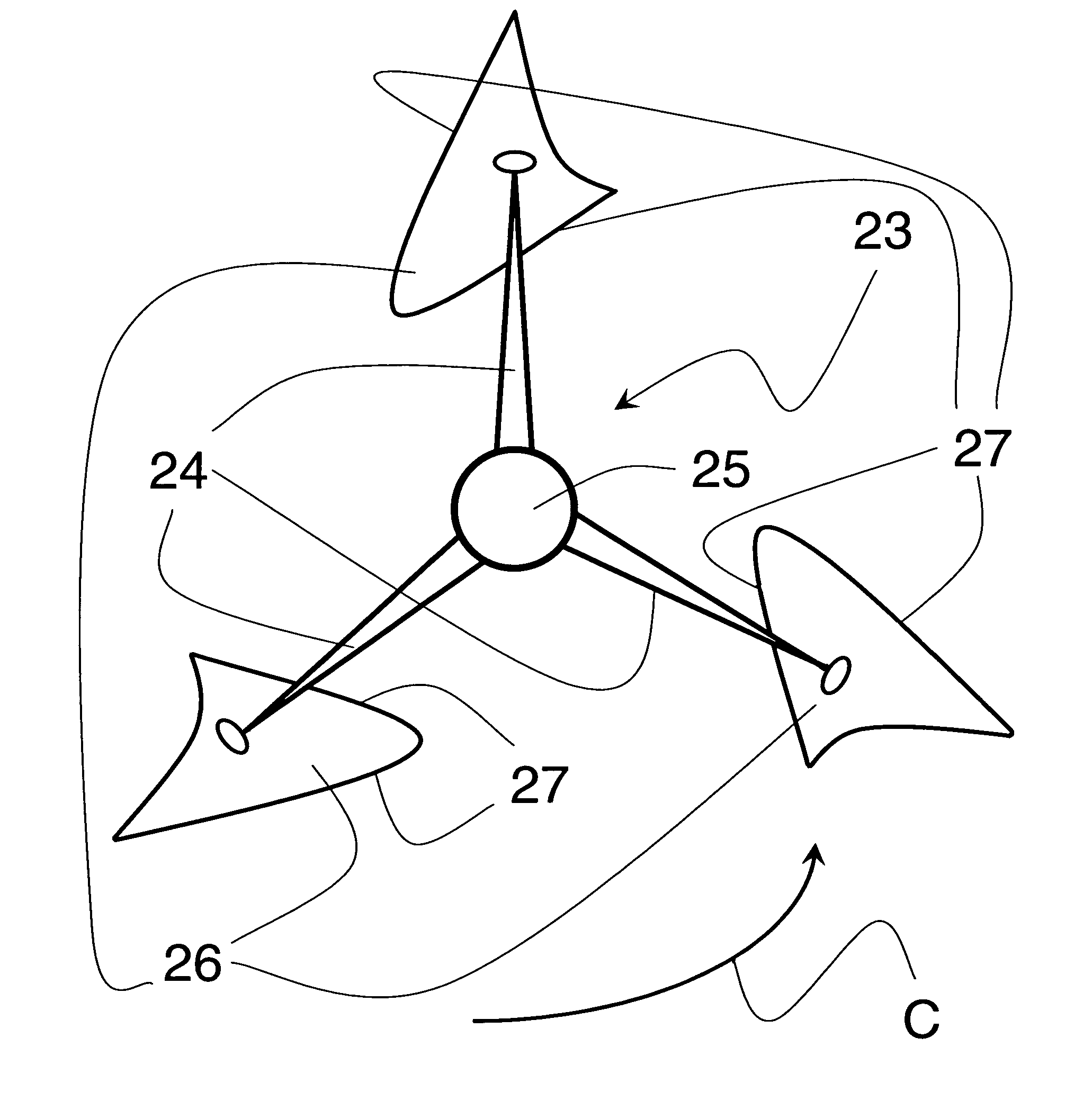
[0017] The present invention exploits the remarkable aerodynamic properties of the Oceanic lateen rig and applies them to wind turbine technology to provide an alternative wind turbine rotor design. The crab claw rig's sail provides a model for the rotor blades of this new rotor. It supplements the prior art, thereby contributing to the overall effort to produce electricity from wind power.

Problems solved by technology

(If the rotor is not perpendicular to the wind, the wind turbine will be much less effective and “yaw error” is said to result.)
The three-bladed rotor type of wind turbine can be costly to construct.
It is possible, nevertheless, that an airplane propeller, though good for propelling an aircraft through the sky, is not the best design for a rotor intended to extract energy from wind.
There are also numerous “vertical axis” wind turbine rotor designs that can be somewhat less efficient because some of the rotor blades are shielded from the wind by the other rotor blades at certain points in the rotation cycle.
Prior art wind turbines utilize merely the true wind energy acting upon their rotor blades and cannot benefit from the apparent wind created by their own rotational movement.
This is a considerable limitation on their performance.

Method used


Image

  • Wind turbine rotor
  • Wind turbine rotor
  • Wind turbine rotor

Examples


Embodiment Construction

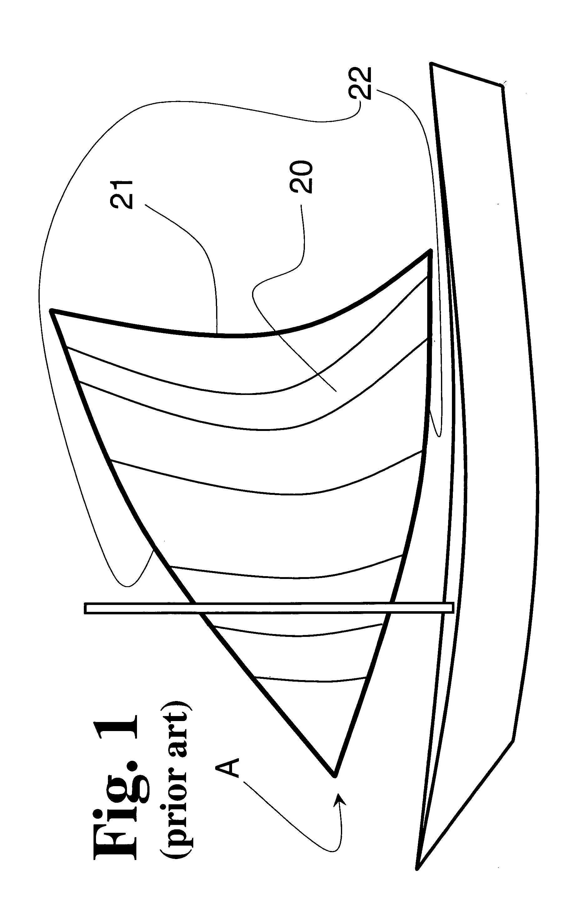
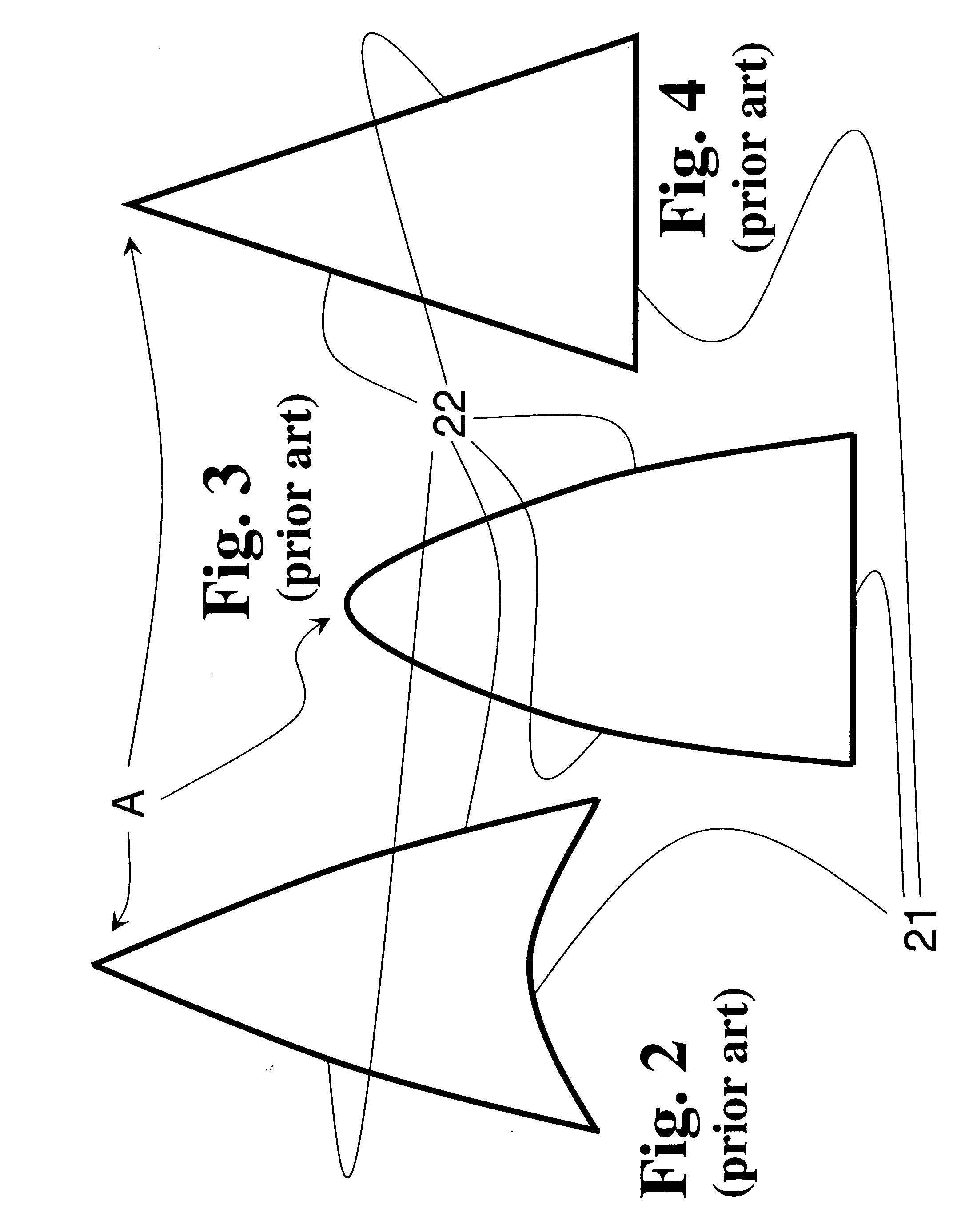
[0025] The basic design of the Oceanic sprit rig and its unique sail is displayed in FIG. 1. A sail 20 of the Oceanic lateen has an arrowhead-like profile with a deeper camber—or curve to the sail—at or near a trailing edge 21. The camber gradually diminishes towards the tip, designated by arrow “A”, where it may disappear entirely. The sail 20 has leading edges 22 forming the other two sides of the arrowhead, and the leading edges 22 lie generally in the same plane. Also, the sail 20 is more or less symmetrical along its longitudinal axis.

[0026] When sailing upwind or on a beam reach, the tip is closer than the trailing edge 21 to the direction the wind is coming from. That is, the tip is in general nearer to the front of the boat than is the trailing edge 21. Also, like other types of sails, the concave side of the sail 20 always faces the wind. That is, the windward side of the sail 20 is concave and the leeward side is convex.

[0027] For a sailboat, the sail of crab claw rig is...


PUM


Abstract

A wind turbine rotor, the rotor blades of which are shaped generally to resemble the sail of an Oceanic sprit rig sailboat (a traditional sailing craft with a sail plan having unusual and significant aerodynamic properties). The rotor blades might be movably mounted to maximize use of apparent wind. An alternative embodiment includes a contra-rotating rotor of similar design.

Description

FIELD OF THE INVENTION [0001] This invention relates to the rotors of wind-driven turbines. More specifically, it concerns rotors for those wind turbines that can produce electrical power when linked to a generator. BACKGROUND OF THE INVENTION [0002] Humans have, for a very long time, tried to harness the kinetic energy in wind and put it to useful purposes. Numerous successful attempts at this have produced valuable labor saving devices. [0003] In modern times, the most sophisticated arrangements for harnessing wind power have resulted in electricity-producing wind turbines. This field of development is increasingly important. As concern about global petroleum supplies and prices continues to grow, and environmental problems associated with the burning of fossil fuels in general yield another set of worries, the promise of renewable and planet-friendly energy sources is immeasurably attractive. [0004] Traditional wind turbines derive their power input by converting some of the wind...

Claims


Application Information

Patent Timeline
Patent Type & Authority Applications(United States)
IPC IPC(8): B63H1/06
CPCF03D3/005F03D3/02Y02E10/74F05B2240/301F03D3/061F03D9/25
Inventor SERPA, MICHAEL LAWRENCE
Owner SERPA MICHAEL LAWRENCE
Learn More