Wind blade spar cap and method of making

a technology of spar cap and wind blade, which is applied in the field of wind blade design and manufacturing methods, can solve the problems of high cost, high cost, and the cost advantage or disadvantage of carbon fiber replacement will depend on the cost ratio of labor to materials, so as to achieve faster resin infusion, less labor, and higher permeability

Inactive Publication Date: 2007-08-16
3TEX
View PDF5 Cites 60 Cited by
  • Summary
  • Abstract
  • Description
  • Claims
  • Application Information

AI Technical Summary

Benefits of technology

[0017] A wind blade spar cap for strengthening a wind blade including an integral, unitary three-dimensional woven material having a first end and a second end, corresponding to a root end of the blade and a tip end of the blade, wherein the material tapers in width from the first to the second end while maintaining a constant thickness and decreasing weight therebetween, the cap being capable of being affixed to the blade for providing increased strength with controlled variation in weight from the root end to the tip end based upon the tapered width of the material thereof.
[0018] An integral, single-piece spar cap having constant thickness and variable width, preferably made from 3-D Woven Carbon / Glass Hybrid material for reducing rotor blade weight and manufacturing cost. An integral, single-piece spar cap having constant thickness and variable width, preferably made from 3-D woven Glass skin material, variable density balsa core sandwich component for reducing rotor blade weight and manufacturing cost. Methods of making the invention are also provided.

Problems solved by technology

In order to achieve these goals, the Cost Of Energy (COE) must come down for wind power because it is not cost-competitive with other energy sources at this time.
While carbon fiber reinforced plastics (CFRP) have superior properties, such as about three times the stiffness with significantly better fatigue properties compared to GFRP, it also has a much higher cost.
In general, the cost advantage or disadvantage of carbon fiber replacement will depend on the cost ratio of labor to materials.

Method used


Image

  • Wind blade spar cap and method of making
  • Wind blade spar cap and method of making
  • Wind blade spar cap and method of making

Examples


Embodiment Construction

[0025] Referring now to the drawings in general, the illustrations are for the purpose of describing a preferred embodiment of the invention and are not intended to limit the invention thereto.

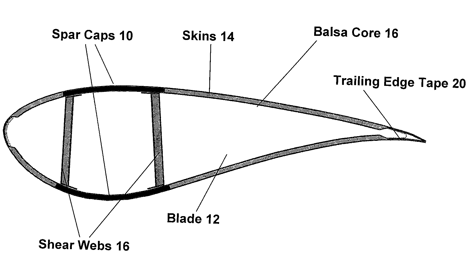
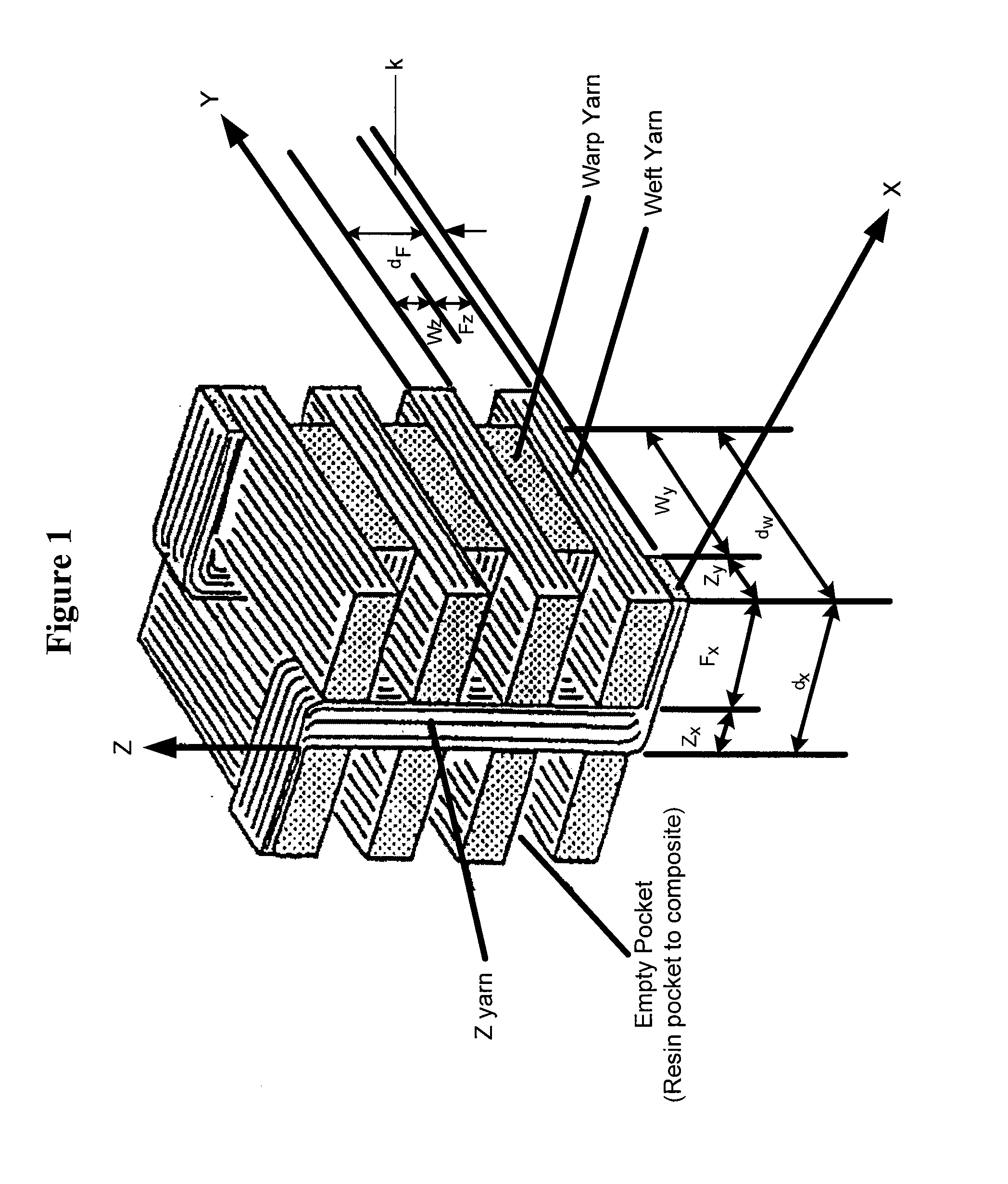
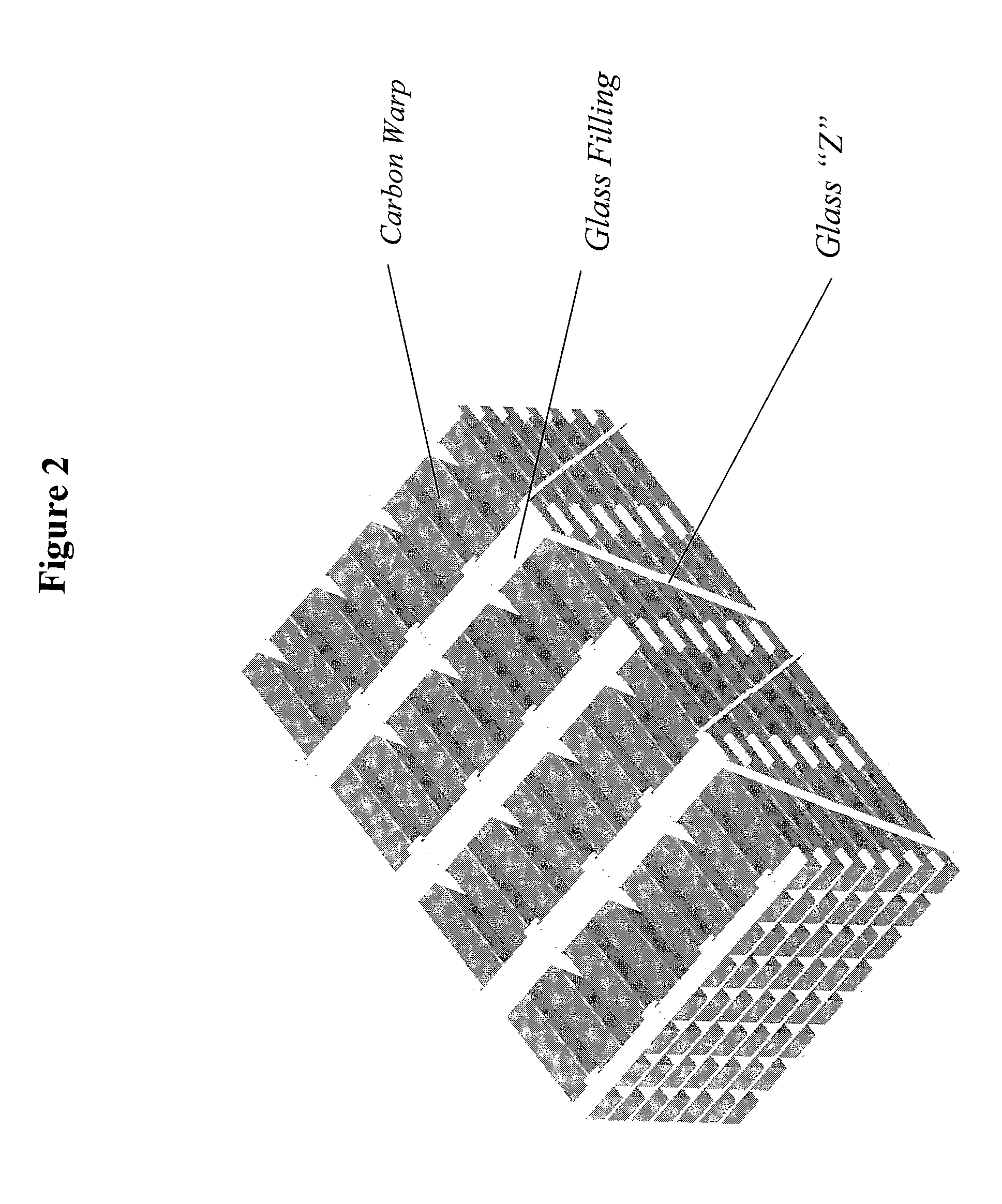
[0026] Traditional spar cap designs and fabrication methods and associated limitations are overcome by the embodiments of the present invention set forth herein. The present invention provides for increased strength and stiffness of wind blades using spar caps formed of 3-D woven fabrics that are moldable and conformable to the wind blade shape and design, without negatively impacting aerodynamic qualities or increasing the weight of the blade. Delamination is also eliminated with the integral, unitary spar cap formed with a 3-D engineered fabric, preferably a 3-D woven fabric, according to the present invention that provides increased stiffness at the root and gradually decreases in weight and coverage moving from the root to the tip of the blade, all without using or incorporating plies of ...


PUM

PropertyMeasurementUnit
lengthaaaaaaaaaa
thicknessaaaaaaaaaa
thicknessaaaaaaaaaa

Abstract

A wind blade spar cap for strengthening a wind blade including an integral, unitary three-dimensional woven material having a first end and a second end, corresponding to a root end of the blade and a tip end of the blade, wherein the material tapers in width from the first to the second end while maintaining a constant thickness and decreasing weight therebetween, the cap being capable of being affixed to the blade for providing increased strength with controlled variation in weight from the root end to the tip end based upon the tapered width of the material thereof. The present inventions also include the method of making the wind blade spar cap and a wind blade including the wind blade spar cap.

Description

STATEMENT AS TO RIGHTS TO INVENTIONS MADE UNDER FEDERALLY-SPONSORED RESEARCH AND DEVELOPMENT [0001] The invention was made in part with Federal funds from the Department of Energy.FIELD OF THE INVENTION [0002] The present invention is directed to wind blades, and more particularly, to wind blade design and manufacturing methods. BACKGROUND OF THE PRIOR ART [0003] The United States Department of Energy has set aggressive goals for increasing the use of wind power in the country. In order to achieve these goals, the Cost Of Energy (COE) must come down for wind power because it is not cost-competitive with other energy sources at this time. Currently, one of the most promising opportunities for significantly reduced COE is through the coordinated development of superior low-cost materials using reliable, high-volume component manufacturing techniques for components used in wind power applications. Rotors, usually consisting of two or three blades attached to a hub, represent the highes...

Claims


Application Information

Patent Timeline
Patent Type & Authority Applications(United States)
IPC IPC(8): B64C27/46B63H1/26D03D15/00D03D25/00
CPCB29C70/24B29L2031/085D10B2101/12D03D15/0011D03D25/005B63H1/26Y02P70/50D03D15/267
Inventor MOHAMED, MANSOUR H.
Owner 3TEX
Why Eureka
Try Eureka