Burning wick structure

a technology of burning wick and wick body, which is applied in the direction of burning wicks, combustion types, combustion processes, etc., can solve the problems of serious affecting the health of the human body, conventional structure is not safe to use, and prone to potential danger, so as to reduce the potential reduce the danger of burning wick. , the effect of improving the effect of insufficient burning of burning liquid

Inactive Publication Date: 2007-08-16
CHEN KUO TUNG
View PDF2 Cites 5 Cited by
  • Summary
  • Abstract
  • Description
  • Claims
  • Application Information

AI Technical Summary

Benefits of technology

[0007] The present invention is to provide a burning wick structure, which is safe to use without hindering the normal effect of the catalytic burning. Further, the possibility of fire caused by accidentally turning over the burning device can be avoided, so that the potential danger of the burning wick can be greatly reduced. Moreover, the insufficient burning of the burning liquid can be effectively improved to avoid the exhausted isopropyl alcohol from being breathed in the human body to affect the heath.

Problems solved by technology

However, such a conventional structure is prone to be potential dangerous since the burning liquid may spill out through the channel when a user accidentally turns over the burning device containing essential oil therein.
Further, when in use, since the isopropyl alcohol contained in the burning liquid may burn insufficiently when heated, the isopropyl alcohol may escape from the open channel to be breathed in the human body.
Therefore, such a conventional structure is not safe to use and seriously affects the health of the human body.

Method used


Image

  • Burning wick structure
  • Burning wick structure
  • Burning wick structure

Examples


Embodiment Construction

[0016] In order to make the Examiner further understand the present invention, the characteristics and the technical contents of the present invention will be explained with reference to the detailed description and the accompanying drawings. However, it should be understood that the drawings are illustrative but not used to limit the scope of the present invention.

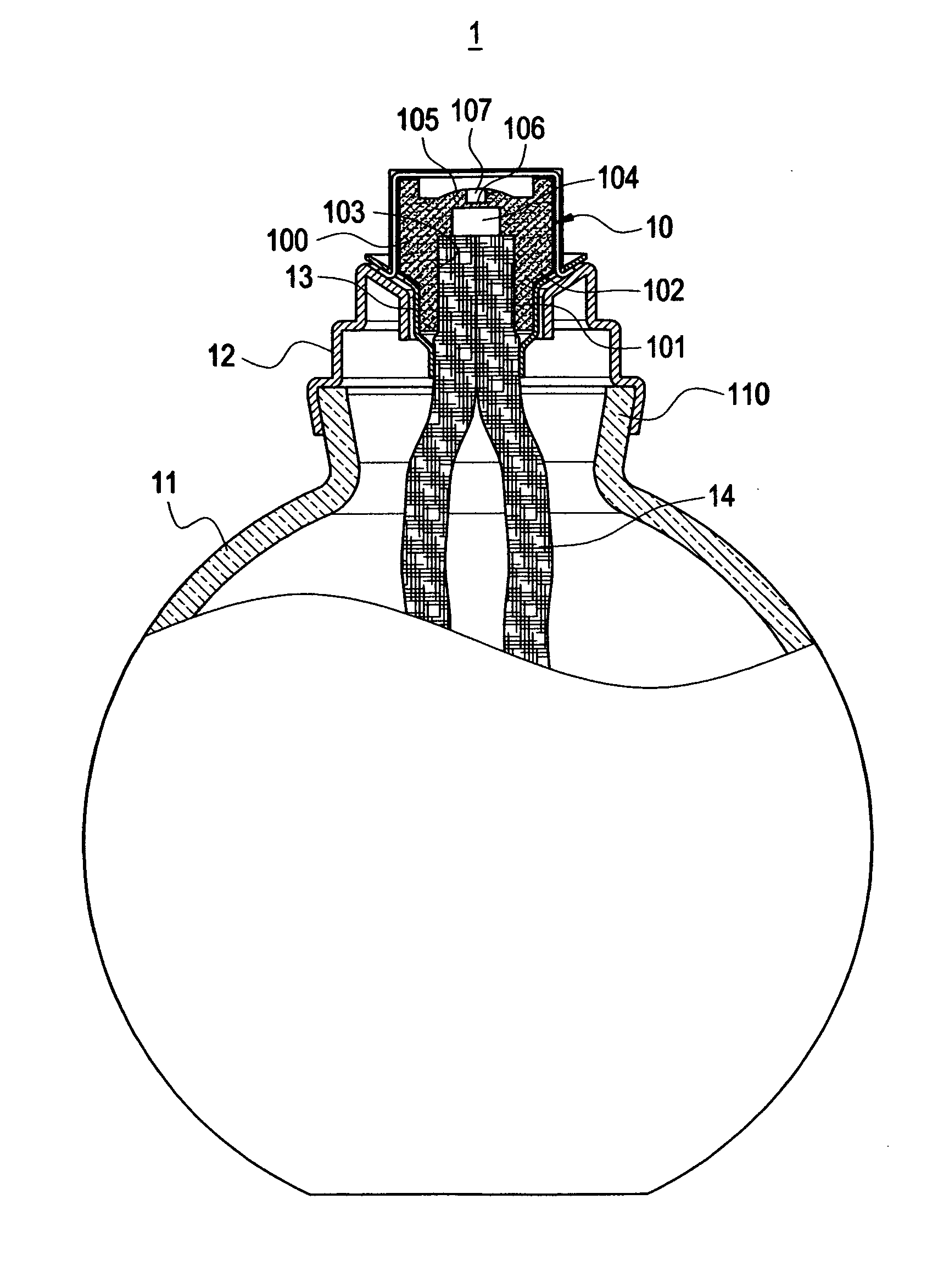
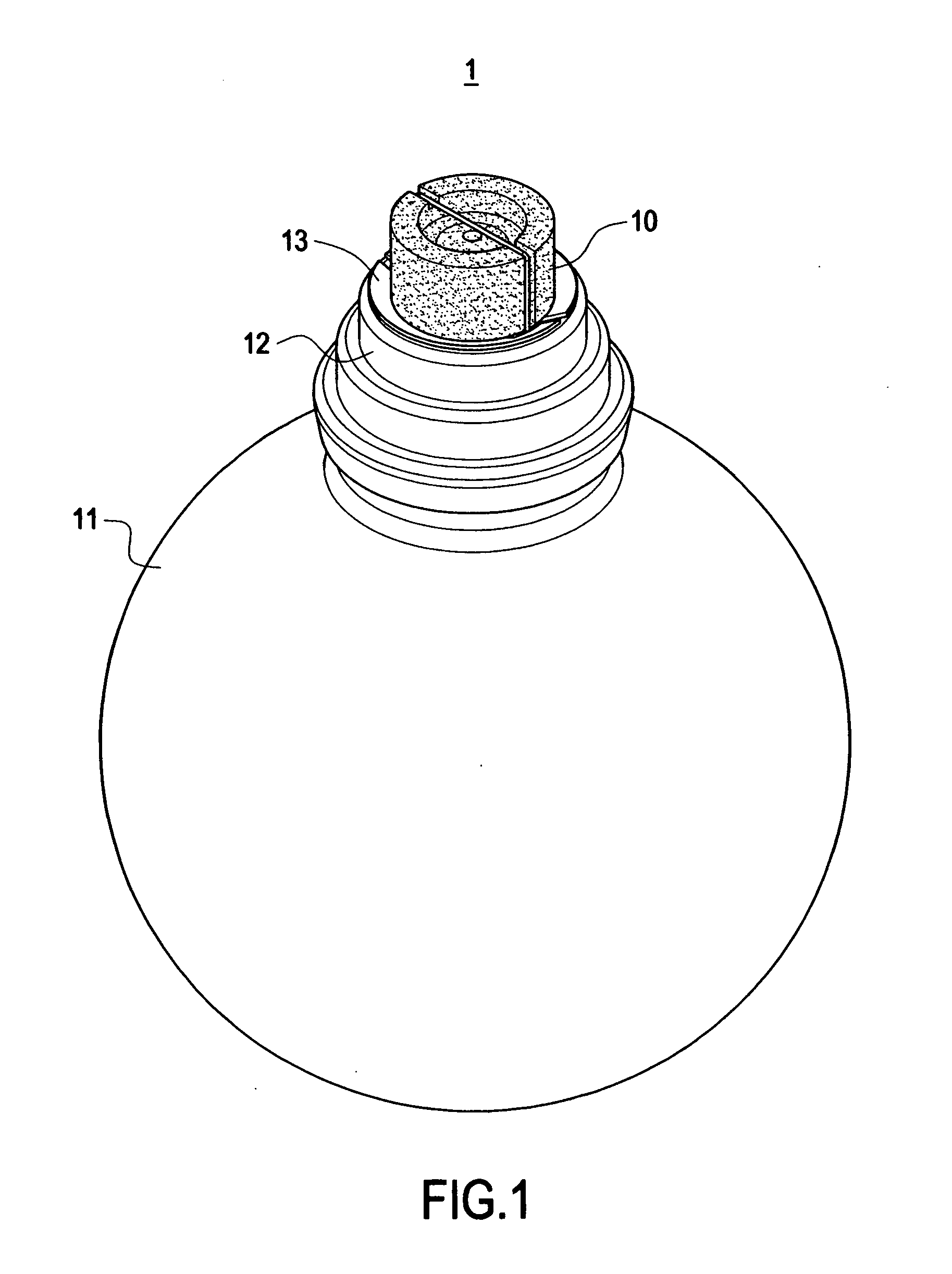
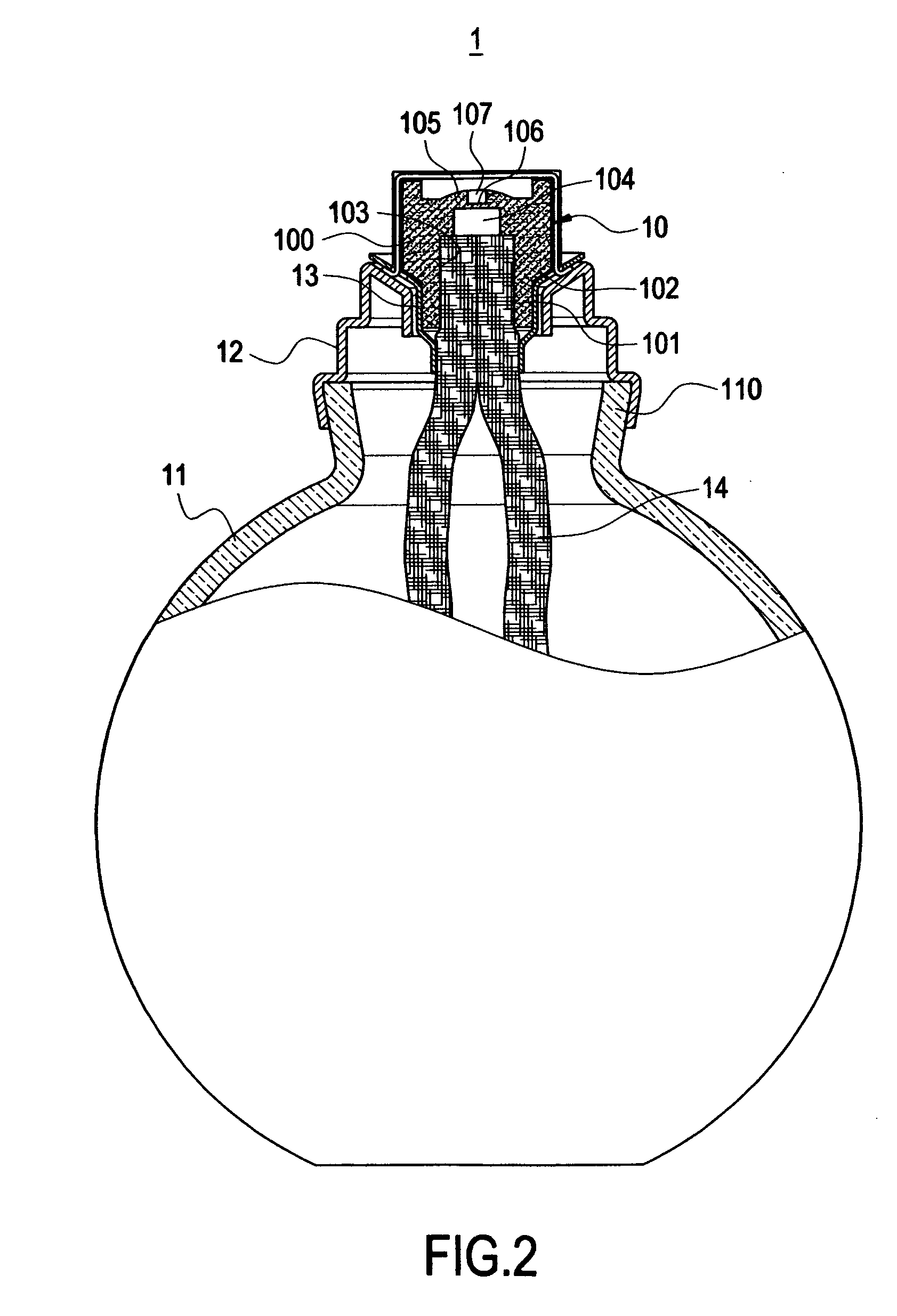
[0017]FIG. 1 is a perspective view showing the external appearance of the burning device of the present invention, and FIG. 2 is a partial cross-sectional view of the burning device of the present invention. The present invention provides an improved structure of burning wick. The burning wick 10 is used for being arranged on a burning device 1 (such as an essential oil lamp). The burning device 1 mainly includes a hollow bottle body 11, a mouth cap 12 provided on a mouth 110 of the bottle body 11, a heat-resistant ring 13 provided on the top portion of the mouth cap 12, and the burning wick 10. The burning wick 10 is su...


PUM


Abstract

A burning wick structure includes an upper half portion and a lower half portion. The outer diameter of the upper half portion is larger than that of the lower half portion. The bottom surface of the lower half portion is provided with an insertion hole for being inserted by an end of a cotton thread. The top portion of the insertion hole is further provided with an evaporating region. A porous region having a larger thickness is formed between the evaporating region and the top portion of the upper half portion. The porous region is formed with at least one ventilating region having a smaller thickness.

Description

BACKGROUND OF THE INVENTION [0001] 1. Field of the Invention [0002] The present invention relates to a burning wick structure, and in particular to a burning wick structure, which is safe to use without hindering the catalytic burning. [0003] 2. Description of Prior Art [0004] Ceramics are water-absorbent by its physical nature, and thus also inherently have porosity and water-absorbency. For example, the standards of purchasing ceramic tiles and bricks must specify the range of the percentage of absorbing water. It is apparent that the water-absorbency of the ceramics is well known. [0005] As disclosed in Taiwan Patent Publication No.474839 entitled “Catalytic Burning Nozzle Having Porous Material”, an open channel is provided on a nozzle, and the channel is in communication with the atmosphere through a hollow portion within the nozzle in order not to hinder the catalytic burning. However, such a conventional structure is prone to be potential dangerous since the burning liquid ma...

Claims


Application Information

Patent Timeline
Patent Type & Authority Applications(United States)
IPC IPC(8): F23D3/18
CPCF23D3/18
Inventor CHEN, KUO-TUNG
Owner CHEN KUO TUNG
Why Eureka
Try Eureka