Control device and method for charging a non-aqueous rechargeable metal-air battery

a non-aqueous rechargeable, control device technology, applied in the direction of batteries, cell components, instruments, etc., can solve the problems of poor capacity retention, sub>2 /sub> is detrimental to the battery, and the battery is not rechargeable in time, so as to prolong the use and anyway safe effect of metal air batteries

Active Publication Date: 2019-08-01
TOYOTA JIDOSHA KK
View PDF0 Cites 3 Cited by
  • Summary
  • Abstract
  • Description
  • Claims
  • Application Information

AI Technical Summary

Benefits of technology

[0014]Currently, it remains desirable to provide a control device which provides a charging control function allowing an extended and anyway safe use of a metal air battery during its lifetime.
[0019]By providing such a configuration it is possible to control charging in dependence on the increase rate of CO2 concentration as a (first) criterion, beside the conventional (second) criterion related to the absolute CO2 concentration detected in the system. The first criterion is related to the rate at which the CO2 will be formed in the battery. This first criterion allows the battery to continue to be charged even if CO2 release already occurred, i.e. the absolute CO2 concentration detected in the system has already increased during lifetime of the battery.
[0021]In other words, the control device can judge whether or not the metal air battery can continue to be charged by detecting the concentration of CO2 and the rate of increase of CO2 concentration. By doing so, expected battery degradation can be prevented and as a result the lifetime of the battery can be extended. Further, the battery can be charged at best and accordingly increase the capacity of charge even in presence of a relatively small amount of CO2 released.
[0022]Moreover, since CO2 emission is an indication that the battery is overcharging and is usually related to a strong increase of voltage which is an indication of an unsafe use of the battery, the control device can provide a safer charging procedure by monitoring during charging both the CO2 concentration and the increase rate of CO2 concentration.
[0037]It has been found that such a relation is a reliable and especially simple criterion to determine whether charging may be continued or not without harming the battery or any unsafe use of the battery.
[0044]In particular the CO2 sensor may be a micro electrochemical system (solid electrolyte type CO2 sensor), a chemical CO2 sensor (for example based on polymer or hetero polysiloxane materials), a non-dispersive infrared absorption CO2 sensor, and / or a gas chromatography-mass spectrometer (GC-MS). Said micro electrochemical system is usually relatively small so that it can be integrated in a chip for example. Another advantage of said system is that the analysis can be carried out for vapors / gases or dissolved species (ionic or non-ionic). Said chemical CO2 sensor has a relatively low energy consumption and provides the possibility to be miniaturized to fit in microelectronics devices.

Problems solved by technology

In such case, bad re-chargeability of the battery occurs and poor capacity retention is observed.
This CO2 is detrimental for the battery since it contributes to the degradation of the battery.
Furthermore, this CO2 is an indication that the battery is overcharging and usually is linked with a strong increase of voltage which is an indication of an unsafe use of the battery.
However, since in such conventional art the threshold value is only set once initially, the battery cannot be charged after the degradation occurred if the concentration of CO2 is already above the threshold value before the battery is charging.

Method used


Image

  • Control device and method for charging a non-aqueous rechargeable metal-air battery
  • Control device and method for charging a non-aqueous rechargeable metal-air battery
  • Control device and method for charging a non-aqueous rechargeable metal-air battery

Examples


Embodiment Construction

[0072]Reference will now be made in detail to exemplary embodiments of the disclosure, examples of which are illustrated in the accompanying drawings. Wherever possible, the same reference numbers will be used throughout the drawings to refer to the same or like parts.

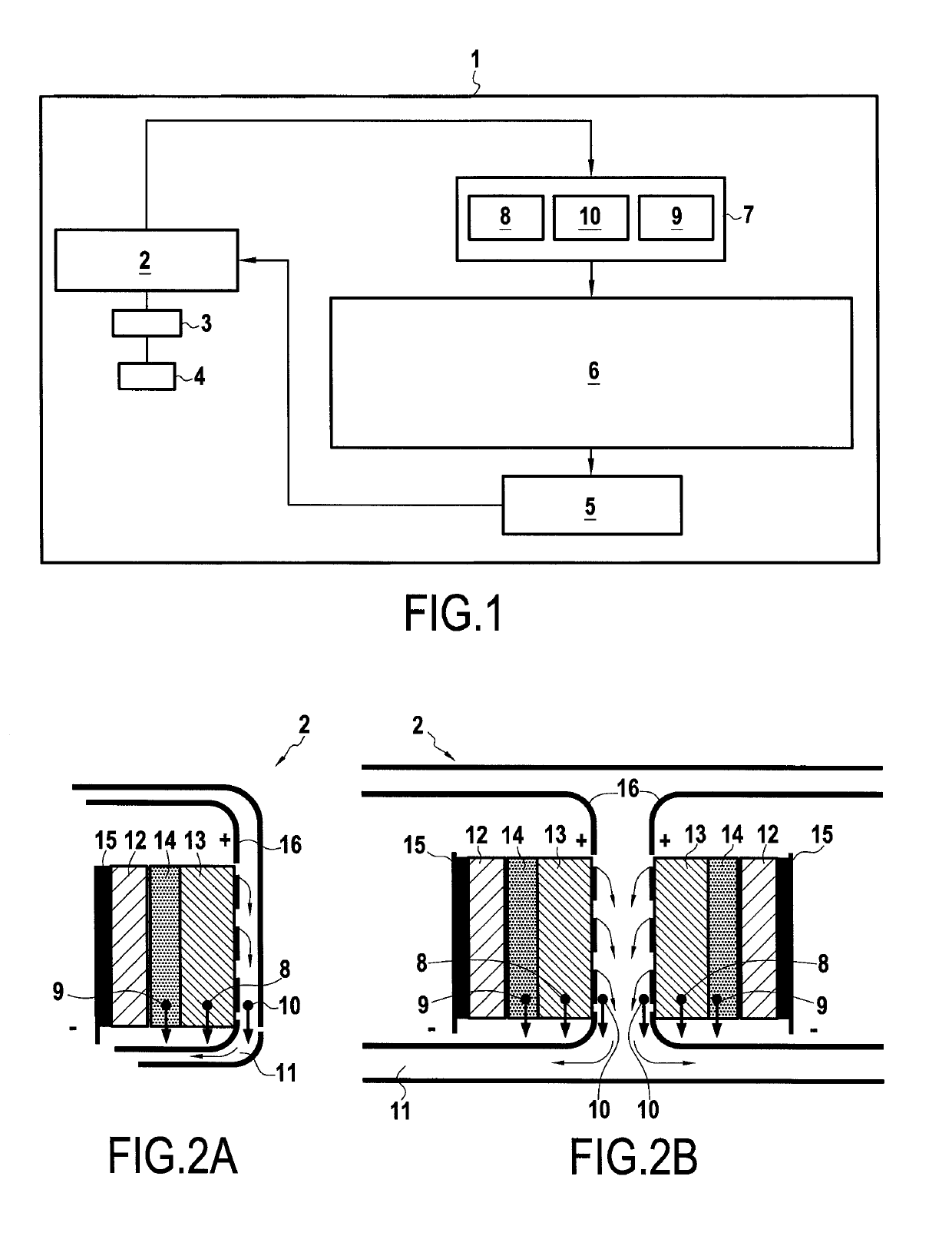
[0073]FIG. 1 shows a schematic representation of a vehicle or a stationary system 1 comprising a control device 6 according to an embodiment of the present disclosure. In the following a vehicle 1 is described, however a stationary system comprises corresponding elements unless indicated in the to following description. The vehicle 1 may be a hybrid vehicle or an electric vehicle (i.e. a purely electrically driven vehicle). The vehicle 1 comprises at least one electric motor 4, which is powered by a battery or battery pack 2, preferably via an inverter 3. In case of a stationary system an electric distribution board 3 is desirably used instead or in addition to the inverter.

[0074]If the vehicle 1 is a hybrid vehicle, i...


PUM

PropertyMeasurementUnit
concentrationaaaaaaaaaa
conductiveaaaaaaaaaa
voltageaaaaaaaaaa

Abstract

A control device for controlling charging of a non-aqueous metal air battery, the control device being configured to: determine a CO2 concentration (Cx) and an increase rate (RCO2) of CO2 concentration in the battery, charge the battery in case both the CO2 concentration (Cx) before starting charging exceeds a predetermined CO2 threshold (CT) and the increase rate of the CO2 concentration (RCO2) during charging is below a predetermined threshold value (ΔCT / ΔAhT, ΔCT / Δt), and stop charging when the increase rate (RCO2) exceeds the predetermined threshold value (ΔCT / ΔAhT, ΔCT / Δt). Also, a corresponding method of controlling charging of a rechargeable battery.

Description

FIELD OF THE DISCLOSURE[0001]The present disclosure is related to a control device for controlling charging of a metal air battery, in particular a non-aqueous rechargeable metal air battery, and also to a method of charging of a non-aqueous metal air battery.BACKGROUND OF THE DISCLOSURE[0002]Rechargeable batteries, also called secondary cells, have become increasingly important as energy storages, in particular for vehicles or stationary applications. Such vehicles may be hybrid vehicles comprising an internal combustion engine and one or more electric motors or purely electrically driven vehicles.[0003]Recently, metal air batteries have become important due to advances in materials technology and an increasing demand for renewable energy sources. A battery may be realized by a single cell but typically it is designed as a battery pack, since it comprises an assembly (in series or parallel) of various modules, themselves composed of several cells.[0004]A metal air battery is usuall...

Claims


Application Information

Patent Timeline
Patent Type & Authority Applications(United States)
IPC IPC(8): H01M12/08H01M12/02G01N33/00
CPCH01M12/08H01M12/02G01N33/004H01M2220/20B60L53/60B60L50/64B60K6/28B60Y2200/91B60Y2200/92B60Y2400/112B60Y2300/91H01M4/382H01M10/441H01M10/482Y02A50/20Y02E60/10Y02T10/70Y02T10/7072Y02T90/12G01N21/00H02J7/00719
Inventor BARDE, FANNYKOMIYAMA, KEITA
Owner TOYOTA JIDOSHA KK
Why Eureka
Try Eureka