Complex hosel structure for a golf club head having a high degree of vibrational absorbability and elastic deformability
a golf club head and complex technology, applied in the field of complex hosel structure for golf club heads with a elastic deformation, can solve the problems of increasing the center of gravity upwardly, affecting the effect of the striking plate, so as to achieve the effect of high degree of vibrational absorbability
- Summary
- Abstract
- Description
- Claims
- Application Information
AI Technical Summary
Benefits of technology
Problems solved by technology
Method used
Image
Examples
first embodiment
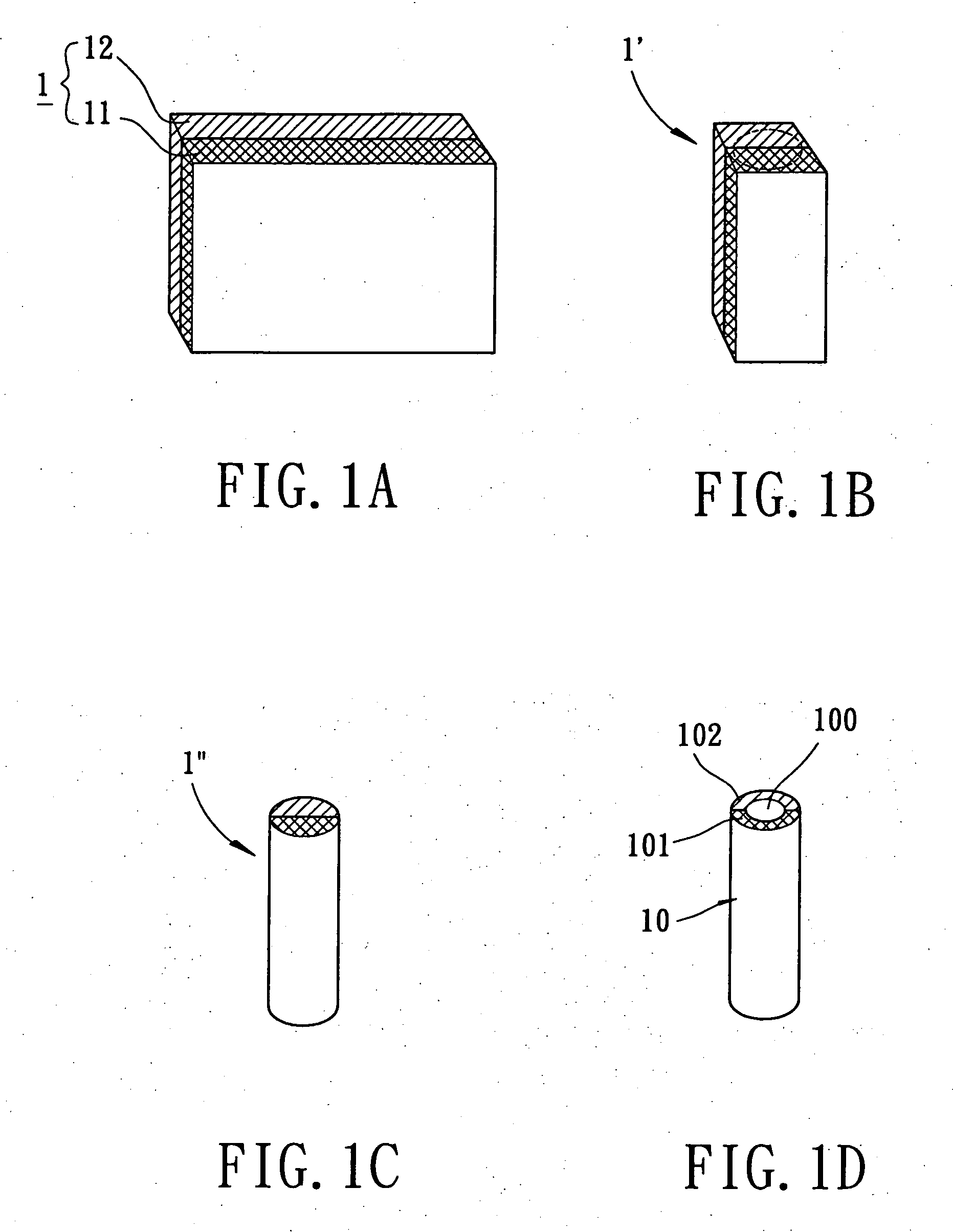
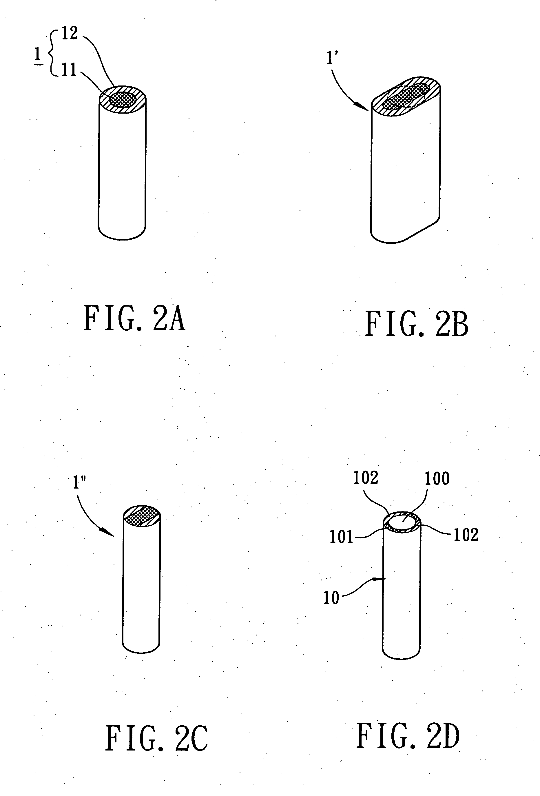
[0031] With reference now to FIGS. 1A through 1D, perspective views of the manufacturing method applied to manufacture the complex hosel structure in accordance with the present invention are illustrated. The manufacturing method for the complex hosel structure includes the steps of: combing a first plate 11 made from a first material with a second plate 12 made from a second material in an explosive welding procedure, a rolling procedure, adhering procedure or a combination thereof to form a complex material 1 of a two-layer plate; cutting the two-layer plate into pieces of complex substrates 1′; forming a one-piece cylindrical member 1″ from the complex substrate 1′; providing a longitudinal through hole in the one-piece cylindrical member 1″ to form a one-piece tubular member as well as the complex hosel 10 by a milling procedure.
[0032] Still referring to FIG. 1A, the first material 11 of the first plate and the second material 12 of the second plate are selected from different m...
sixth embodiment
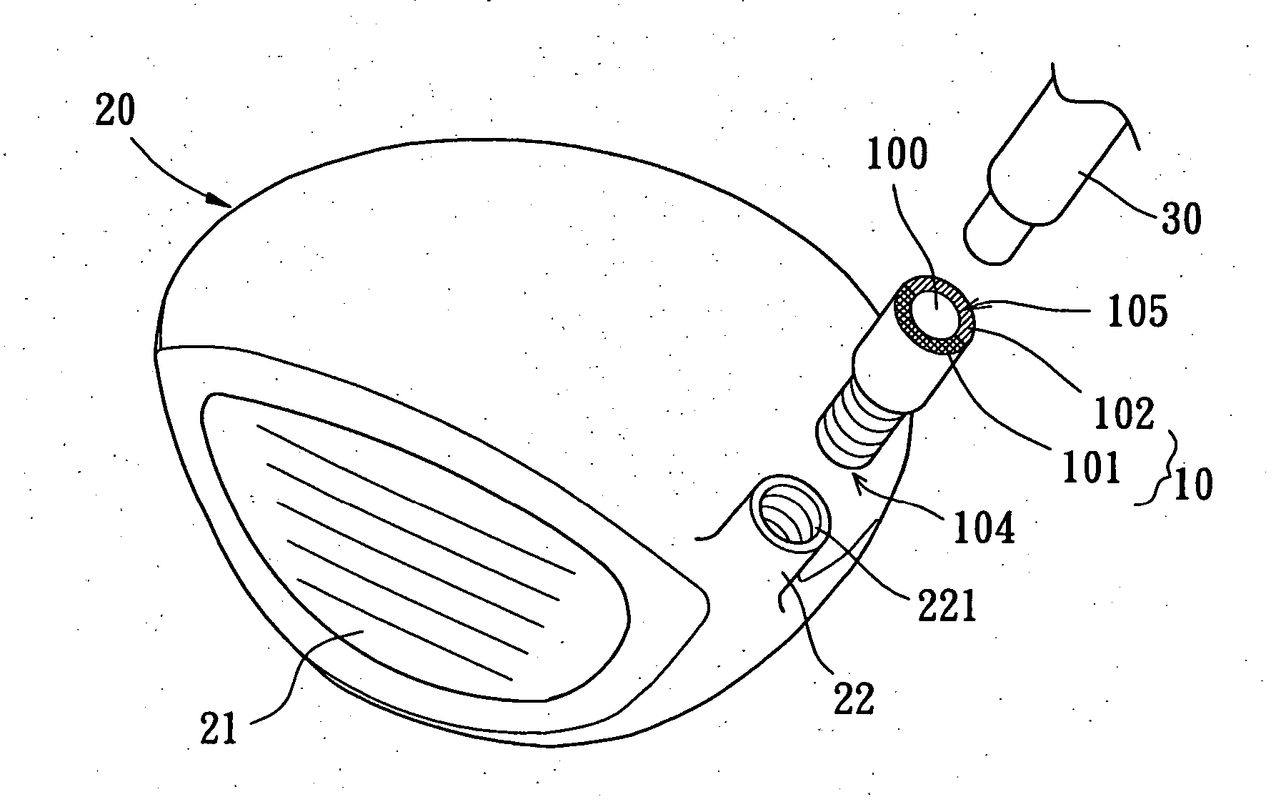
[0042] Referring to FIG. 6, in the sixth embodiment, the connecting portion 221 of the golf club head body 20 is provided with a screw hole formed with an inner threaded portion while the first connecting portion 104 of the complex hosel 10 is correspondingly provided with a screw rod formed with an outer threaded portion. In an alternative embodiment, the screw hole disposed on the connecting portion 221 of the golf club head body 20 is interchanged with a screw rod while the screw rod disposed on the first connecting portion 104 of the complex hosel 10 is interchanged with a screw hole. Namely, the first connecting portion 104 of the complex hosel 10 can be provided with a screw rod while the connecting portion 221 of the golf club head body 20 can be correspondingly provided with a screw hole. Once assembled, the complex hosel 10 and the neck portion 22 of the golf club head body 20 are aligned with each other in an angled relationship. Accordingly, each orientation of the first ...
seventh embodiment
[0043] Turning now to FIG. 7, in the seventh embodiment, the golf club head body 20 is selected from the iron-type club head. The connecting portion 221 of the golf club head body 20 is provided with an engaging rod projected therefrom while the first connecting portion 104 of the complex hosel 10 is correspondingly provided with an engaging hole formed in the hollow section 100. In an alternative embodiment, the engaging rod disposed on the connecting portion 221 of the golf club head body 20 is interchanged with an engaging hole while the engaging hole disposed in the first connecting portion 104 of the complex hosel 10 is interchanged with an engaging rod. Namely, the first connecting portion 104 of the complex hosel 10 can be provided with an engaging hole while the connecting portion 221 of the golf club head body 20 can be correspondingly provided with an engaging rod. Once assembled, the complex hosel 10 and the neck portion 22 of the golf club head body 20 are aligned with e...
PUM
 Abstract
Description
Claims
Application Information
 - R&D
- Intellectual Property
- Life Sciences
- Materials
- Tech Scout
- Unparalleled Data Quality
- Higher Quality Content
- 60% Fewer Hallucinations
Browse by: Latest US Patents, China's latest patents, Technical Efficacy Thesaurus, Application Domain, Technology Topic, Popular Technical Reports.
© 2025 PatSnap. All rights reserved.Legal|Privacy policy|Modern Slavery Act Transparency Statement|Sitemap|About US| Contact US: help@patsnap.com


