Design method of metal rubber shock absorber for pipe support

A metal rubber and pipe support technology, which is applied in the direction of instruments, calculations, special data processing applications, etc., can solve the problems of unsatisfactory vibration reduction effect and long-term service, and achieve good elasticity and damping performance, not easy to fatigue, and high vibration absorption performance Effect

Active Publication Date: 2015-08-26
UNIV OF SCI & TECH BEIJING
View PDF3 Cites 2 Cited by
  • Summary
  • Abstract
  • Description
  • Claims
  • Application Information

AI Technical Summary

Problems solved by technology

[0003] In order to overcome the defect that the existing ordinary shock absorbers cannot serve for a long time in harsh and harsh working environments such as high temperature, low temperature, corrosive atmosphere, and radiation, and the vibration damping effect is not ideal, a high temperature resistant, low temperature resistant, large damping The design method of the metal rubber shock absorber with excellent vibration damping performance that does not change with temperature, corrosion resistance, radiation resistance, long life in harsh environments, and high stability

Method used


Image

  • Design method of metal rubber shock absorber for pipe support
  • Design method of metal rubber shock absorber for pipe support
  • Design method of metal rubber shock absorber for pipe support

Examples


Embodiment

[0083] Take the pipe with a self-weight of 200KG as an example, the relationship between the actual calculated surface pressure and angle is:

[0084] P=0.45154+9.21383e -4 Theta-2.05334e -4 θ 2 +1.54798e -6 θ 3 ;

[0085] The number of blocks arranged in the lower half of the shock absorber is 9, then 1<

[0086] Then the angle occupied by each piece of metal rubber block: Δθ=20°;

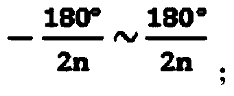
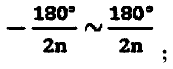
[0087] The angle range of the 0th metal rubber block is: -10°~10°;

[0088] The angle range of the ±i metal rubber block is: ±{[10°+(i-1)*20°]~[10°+i*20°]};

[0089] The contact area between each piece of metal rubber block and the pipe:

[0090]

[0091] The positive pressure on the contact surface between the 0th and ±i metal rubber blocks and the pipe is as follows:

[0092]

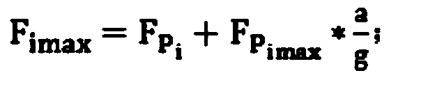
[0093] The pipeline vibration acceleration is: a=2πf 2 A=(2π*50Hz) 2 *6e -5 m≈6m / s 2 ;

[0094] The maximum pressure of the ±i metal rubber block is: The maximum pressure is: P imax =F imax / ...

specific Embodiment approach 1

[0107] Specific implementation mode one: as attached figure 2 As shown, when the nominal diameter of the pipeline is small, it is installed in the form of a single suspender, that is, the wire suspender connects the present invention with the roof base plate through the top screw joint of the upper pipe clamp to form a hanger.

specific Embodiment approach 2

[0108] Specific implementation mode two: as attached image 3 As shown, when the nominal diameter of the pipeline is relatively large, it is installed in the form of double suspenders, that is, the wire suspenders connect the present invention with the roof base plate through the screw joints on both sides of the upper pipe clamp to form a hanger.


PUM


Abstract

The present invention discloses a design method of a metal rubber shock absorber for pipe support. According to the method, different molding densities are employed for the shock absorber blocks at different positions along a circumferential direction of a pipeline; according to a basic law that the smaller the molding density of the metal rubber, the smaller the support rigidness, and the better the shock absorption performance, a metal rubber shock absorber block having a greater molding density is used at a position under a greater pressure to improve the support rigidness, and a metal rubber shock absorber block having a small molding density is used at a position under a small pressure to improve the shock absorption performance. In this way, under the circumstances of ensuring safe serving of the entire shock absorber, a more reasonable shock absorption effect is achieved. According to the present invention, a plurality of rectangular-approximate shock absorber blocks having different densities are employed and are embedded between a plurality of limiting plates in the pipe. The internally-interconnected spatial mesh structure of the shock absorber block ensures good elasticity and damping performance. The shock absorber blocks at different positions employ different densities under the pressure distribution caused by self-weights, so as to obtain a better shock absorption effect.

Description

Technical field: [0001] The invention relates to a shock absorber, in particular to a design method of a pipe-supported metal rubber shock absorber. Background technique: [0002] At present, ordinary vibration damping materials used in ordinary shock absorbers cannot serve for a long time in harsh and harsh working environments such as high temperature, low temperature, corrosive atmosphere, and radiation. Under harsh environments, the material becomes embrittled, hardened, and the material performance drops or even fails after corrosion. It not only affects the vibration reduction effect, but even affects the safety of personnel and equipment. On the other hand, most of the existing general pipeline dampers are designed in the shape of a ring, with large shape and size, high production cost, difficult assembly, difficult disassembly and maintenance, and the damping effect is not ideal at the same time. The overall design of the damping material has not considered Due to t...

Claims


Application Information

Patent Timeline
Patent Type & Authority Applications(China)
IPC IPC(8): G06F17/50
Inventor 李静媛王鹏卢成壮陈雨来
Owner UNIV OF SCI & TECH BEIJING
Why Eureka
Try Eureka