Combustion chamber in a turbomachine

a combustion chamber and turbomachine technology, which is applied in the direction of machines/engines, mechanical equipment, lighting and heating apparatus, etc., can solve the problems of cracks and reduce the lifetime of the combustion chamber, and achieve the effect of simple, effective and inexpensiv

Active Publication Date: 2007-08-23
SN DETUDE & DE CONSTR DE MOTEURS DAVIATION S N E C M A
View PDF5 Cites 43 Cited by
  • Summary
  • Abstract
  • Description
  • Claims
  • Application Information

AI Technical Summary

Benefits of technology

[0007]A particular object of the invention is to provide a solution to these problems that is simple, effective, and inexpensive.

Problems solved by technology

When the turbomachine is in operation, the inner and outer walls of the combustion chamber expand thermally and are subjected to high levels of vibration, thereby generating high stresses at the edges of the orifices, which can lead to cracks appearing in said edges, and can thus reduce the lifetime of the combustion chamber.
The combustion chamber walls may also include inclined multiperforations for passing cooling air that are formed at a distance from the projecting edges of the orifices and that do not provide adequate cooling in the immediate vicinity of said orifices.
In these zones, the temperatures reached lead to local burning and corrosion of the metal, thereby leading to the appearance of cracks.

Method used


Image

  • Combustion chamber in a turbomachine
  • Combustion chamber in a turbomachine
  • Combustion chamber in a turbomachine

Examples


Embodiment Construction

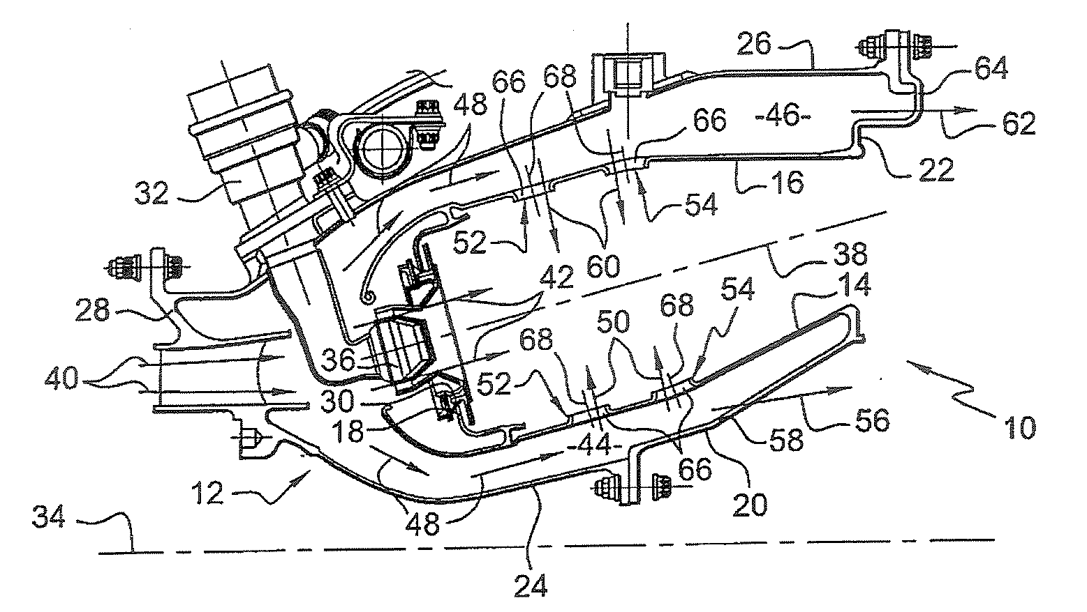
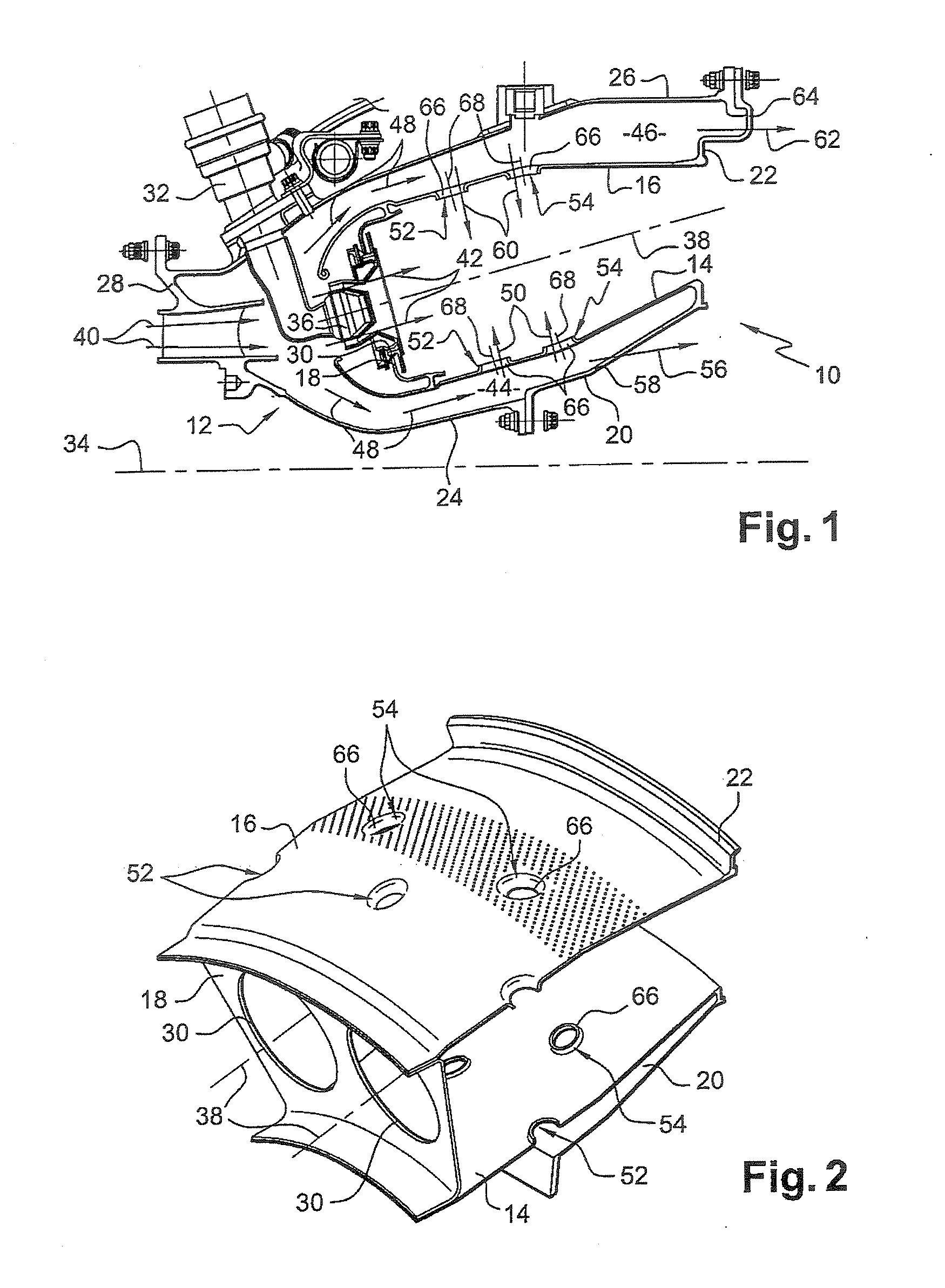
[0025]In FIG. 1, a turbomachine combustion chamber 10 is disposed at the outlet of a diffuser 12, itself situated at the outlet from a compressor (not shown), and it comprises inner and outer circularly-symmetrical walls 14 and 16 connected upstream to an annular chamber end wall 18 and secured downstream via inner and outer annular flanges 20 and 22 respectively to an inner frustoconical web 24 of the diffuser and to one end of an outer casing 26 of the chamber, the upstream end of the casing 26 being connected to an outer frustoconical web 28 of the diffuser.

[0026]The annular chamber end wall 18 has openings 30 (FIGS. 1 and 2) through which there pass both air coming from the diffuser 12 and fuel delivered by injectors 32 secured to the outer casing 26 and regularly distributed around a circumference about the longitudinal axis 34 of the chamber. Each injector 32 has a fuel injection head 36 mounted in an opening 30 of the annular wall 18 and in alignment with the axis 38 of said ...


PUM


Abstract

A turbomachine combustion chamber has primary and dilution air inlet orifices formed by die stamping to have edges that project into the inside of the combustion chamber, and stress relaxation and/or reduction means in the edges or in the vicinity of the edges of said orifices, said means comprising, for each orifice, one, two, or three slots formed in the edge or around a fraction of the edge of said orifice.

Description

[0001]The present invention relates to an annular combustion chamber for a turbomachine such as an aircraft turbojet or turboprop.BACKGROUND OF THE INVENTION[0002]Such a combustion chamber has coaxial circularly-symmetrical walls extending one inside the other and interconnected at their upstream ends by an annular chamber end wall that has openings for feeding air and for fuel delivery means.[0003]The inner and outer walls of the chamber include inlet openings and for primary air and dilution air, said openings having edges that project into the inside of the chamber in order to improve the penetration of air into the chamber and in order to guide said air into the very core of the combustion area of the chamber.[0004]These air inlet orifices are usually circular in shape and made by die stamping, which has the effect of creating zones of high stress concentration in the edges of the orifices.[0005]When the turbomachine is in operation, the inner and outer walls of the combustion c...

Claims


Application Information

Patent Timeline
Patent Type & Authority Applications(United States)
IPC IPC(8): F02C3/00
CPCF23D2211/00Y02T50/675F23R2900/00005F23R3/06Y02T50/60
Inventor BESSAGNET, FLORIAN ANDRE FRANCOISCOMMARET, PATRICE ANDREDE SOUSA, MARIO CESARHERNANDEZ, DIDIER HIPPOLYTE
Owner SN DETUDE & DE CONSTR DE MOTEURS DAVIATION S N E C M A
Why Eureka
Try Eureka