Tape-wrapped multilayer tubing and methods for making the same

a multi-layer tubing and tape wrapping technology, applied in the direction of pipe protection by thermal insulation, synthetic resin layered products, pipes, etc., can solve the problems of high heat dissipation requirements of modern high-performance processors, and difficult to meet the requirements of traditional designs. achieve the effect of efficient production of multi-layer tape wrapping tubing

Active Publication Date: 2007-08-23
VERTIV CORP
View PDF99 Cites 15 Cited by
  • Summary
  • Abstract
  • Description
  • Claims
  • Application Information

AI Technical Summary

Benefits of technology

[0010] Embodiments of the present invention are directed to a hybrid multilayer tube construction that combines high flexibility with a barrier to diffusion and low water vapor transmission rates. It is, therefore, an object of this invention to provide a tape-wrapped multilayer tubing that is flexible and which has an effective vapor diffusion barrier and also a method for making such tubing in a continuous and in-line process.
[0012] Another aspect of the invention is a method for efficiently making the multi-layer tape wrapped tubing in an in-line and continuous process. First the inner tubing and the diffusion barrier tape are guided to a wrapper apparatus. The wrapper wraps the tubing with the diffusion barrier tape and a seam is created. The diffusion barrier tape wrapped inner tubing is then guided to a sealer apparatus to seal the seam. The sealed, diffusion barrier tape wrapped inner tubing is then guided to an extruder where the outer jacket layer is extruded onto the tubing.

Problems solved by technology

Fluid diffusion is a problem in such systems, particularly in closed systems, whether the losses are due to water vapor transmission or the loss of the fluid components of a mixture.
Another example of this problem arises in the field of cooling systems for electronics.
As this need grows it is presenting significant challenges to traditional designs.
Moreover, modern high performance processors have very high heat dissipation requirements.
However, the traditional cooling methods, which include fan mounted heat sinks and heat pipes, have a number of limitations.
Fan mounted heat sinks often do not move air quickly enough to cool a modern processor, or do not sufficiently move hot air out of the casing holding the electronics.
Similarly, heat pipes are limited in the amount of heat they can dissipate, and the distance they can move the heat from the heat source.
Hence, conventional cooling techniques that use heat pipes or fan mounted heat sinks are not adequate for cooling modern electronics, such as high performance processors.
Diffusion of vapor in a liquid cooling system is a problem, and potentially catastrophic if the system is allowed to dry up.
In a liquid cooling system that uses a radiator, the loss of fluid results in a gradual loss of thermal performance.
Furthermore, in a liquid cooling system where fluid is pumped, the substantial loss of fluid eventually results in overheating.
The use of such tubing presents design challenges due to its rigid nature, the expense of metal, and the difficulty in assembly.
Furthermore, any mixing of metals in such a system leads to corrosion and clogging in the tubes, pump or radiator.

Method used


Image

  • Tape-wrapped multilayer tubing and methods for making the same
  • Tape-wrapped multilayer tubing and methods for making the same
  • Tape-wrapped multilayer tubing and methods for making the same

Examples


Embodiment Construction

[0032] In the following description, numerous details are set forth for purpose of explanation. However, one of ordinary skill in the art will realize that the invention can be practiced without the use of these specific details.

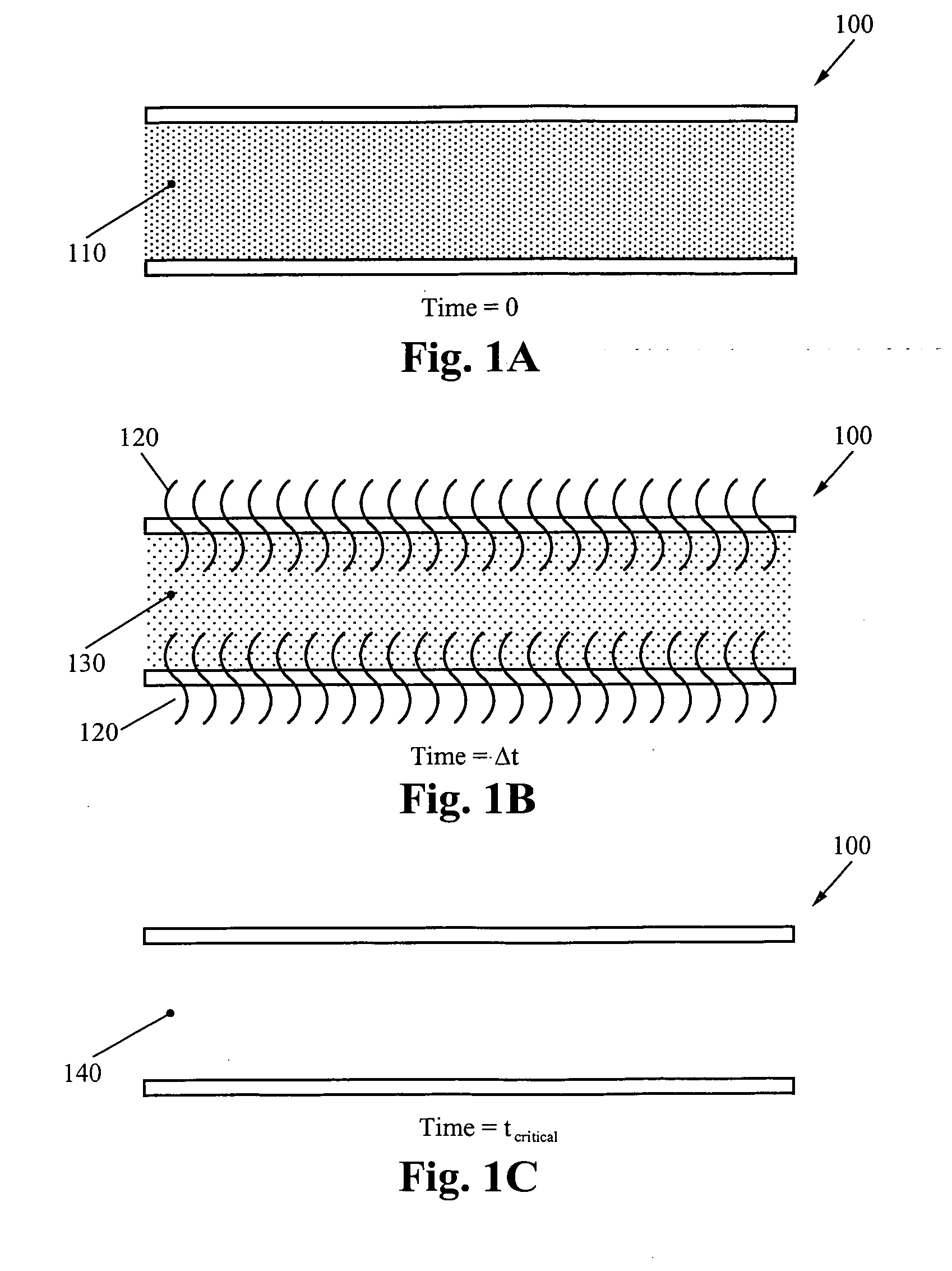
[0033]FIGS. 1A through 1C facilitate the understanding of the invention by illustrating how liquid is lost in a cooling system using ordinary polymer tubing due to diffusion of vapor. FIG. 1A shows a polymer tube 100 filled with some original amount of vapor 110 at time (t)=0. The vapor 110 is 100% of the original water vapor in the system.

[0034]FIG. 1B represents the same polymer tube 100 at some later time t=Δt after time (t)=0. At time t=Δt, some vapor has diffused through the polymer tube walls because there is a higher concentration of vapor inside the tube than outside the tube. The diffused particles 120 escape the system. When this occurs, the amount of vapor 130 in the polymer tube 100 is less than the original amount of vapor 110. FIG. 1C illustr...


PUM

PropertyMeasurementUnit
lengthaaaaaaaaaa
lengthaaaaaaaaaa
thicknessaaaaaaaaaa

Abstract

The multi-layer tape wrapped tubing for effectively impeding the diffusion of vapor is made in a continuous in-line process and has three distinct layers: an inner tubing layer, a middle diffusion barrier layer and an outer jacketing layer. The inner tubing layer comes into contact with liquid and vapor. Vapor that might ordinarily diffuse through the tubing is impeded by the diffusion barrier layer. The diffusion barrier layer is a laminate comprising a diffusion barrier film with a very low vapor diffusion rate sandwiched between layers of thermoplastic. The diffusion barrier layer is wrapped around the inner tubing one or more times. The outer jacket layer is a polymeric jacket which is extruded onto the diffusion barrier layer wrapped inner tubing.

Description

RELATED APPLICATIONS [0001] This application claims priority under 35 U.S.C. section 119(e) of co-pending U.S. Provisional Patent Application No. 60 / 763,566, filed Jan. 30, 2006, and entitled “Taped-wraped Multilayer Tubing and Methods Making The Same,” which is hereby incorporated by reference.FIELD OF THE INVENTION [0002] The present invention is related fluid transport systems to prevent fluid diffusion losses. Specifically, the present invention is related to tape-wrapped multilayer tubing for use in a liquid cooling system and a method for making the same. BACKGROUND [0003] Many types of fluid transport systems exist which require tubing to transport fluid between points in a system. Fluid diffusion is a problem in such systems, particularly in closed systems, whether the losses are due to water vapor transmission or the loss of the fluid components of a mixture. For example, if three components form a fluid mixture and each component has a different diffusion rate or permeabil...

Claims


Application Information

Patent Timeline
Patent Type & Authority Applications(United States)
IPC IPC(8): F16L11/00B29C48/09B29C48/151B29C48/21
CPCB29C65/18B29C47/065B29D23/001B29K2101/12B29K2995/0069B29L2009/00B29L2023/22B32B1/08F16L11/04F16L59/029F16L2011/047B29C47/0023B29C47/021B29C63/065B32B15/08B32B15/20B32B25/08B32B27/08B32B27/32B32B27/34B32B2307/5825B32B2307/7246B32B2597/00Y10S138/10B29C47/0064B29C66/83413B29C66/4322B29C66/73715B29C65/02B29C66/7234B29C66/72321B29C66/71B29C66/133B29C48/09B29C48/0021B29C48/151B29C48/21B29C48/276Y02P70/10B29K2077/00B29K2067/00B29K2027/14B29K2027/12B29K2027/08B29K2025/06B29K2023/16B29K2023/0633B29K2023/06B29K2023/00B29K2021/003B29K2019/00B29K2009/06B29K2009/00
Inventor WERNER, DOUGLASFIROUZI, ALIMUNCH, MARKCICHOCKI, ZBIGNIEW
Owner VERTIV CORP
Why Eureka
Try Eureka