
Reciprocating conveyor system and method

a conveyor and reciprocating technology, applied in conveyors, conveyors, jigging conveyors, etc., can solve the problems of difficult control, known linear motor types, and difficult to achieve desirable acceleration rates in the conveying portion of the conveyor operating cycle, and in the slip portion of the cycle, so as to achieve the effect of reducing the generation of frictional hea

Inactive Publication Date: 2007-08-23
TRIPLES DYNAMICS
View PDF23 Cites 9 Cited by
  • Summary
  • Abstract
  • Description
  • Claims
  • Application Information

AI Technical Summary

Benefits of technology

"The present invention provides an improved conveyor system for conveying solid materials and articles along a conveyor tray in a horizontal and linear direction. The conveyor system minimizes vibration and frictional heat, and includes a linear electric motor that moves the conveyor tray in a smooth and stable manner. The conveyor system can be controlled to move in a desired direction and at a desired speed. The invention also provides an improved method of operating the conveyor system. Overall, the invention provides a more efficient and effective conveyor system for solid materials."

Problems solved by technology

Both types of conveyors of the general type use known components and apparatus which require frequent maintenance, due at least in part to the nature of the motion of the conveyor system and friction generated by the drive mechanism.
Known types of linear motors are difficult to control to produce a high enough acceleration of the conveyor tray or pan on the slip portion of the cycle so as to easily exceed the coefficient of friction between the material or article being conveyed and the conveyor pan or tray surface while also maintaining acceleration low enough to minimize adverse stresses on the conveyor system.
Moreover, desirable rates of acceleration in the conveying portion of the conveyor operating cycle, as well as in the slip portion of the cycle, have been difficult to achieve heretofore.

Method used


Image

  • Reciprocating conveyor system and method
  • Reciprocating conveyor system and method
  • Reciprocating conveyor system and method

Examples


Embodiment Construction

[0022] In description which follows like parts are marked throughout the specification and drawing with the same reference numerals, respectively. The drawing figures are not necessarily to scale and certain features may be shown in generalized or schematic form in the interest of clarity and conciseness.

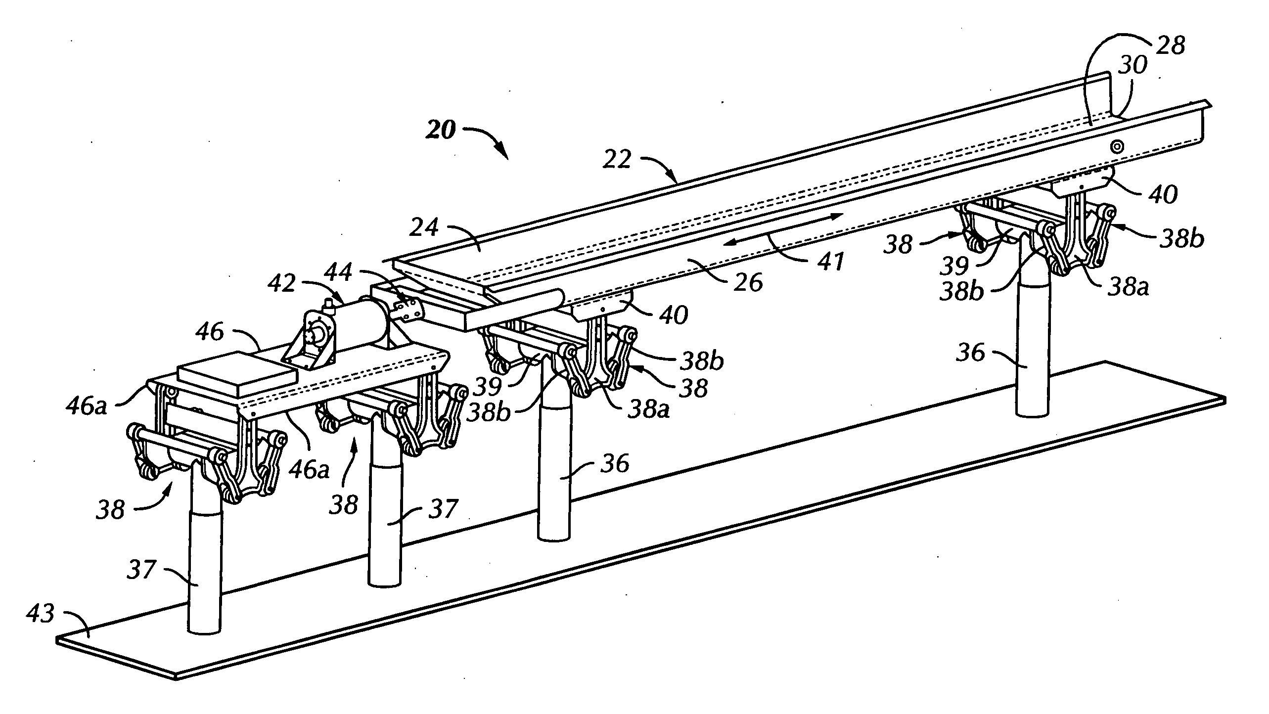
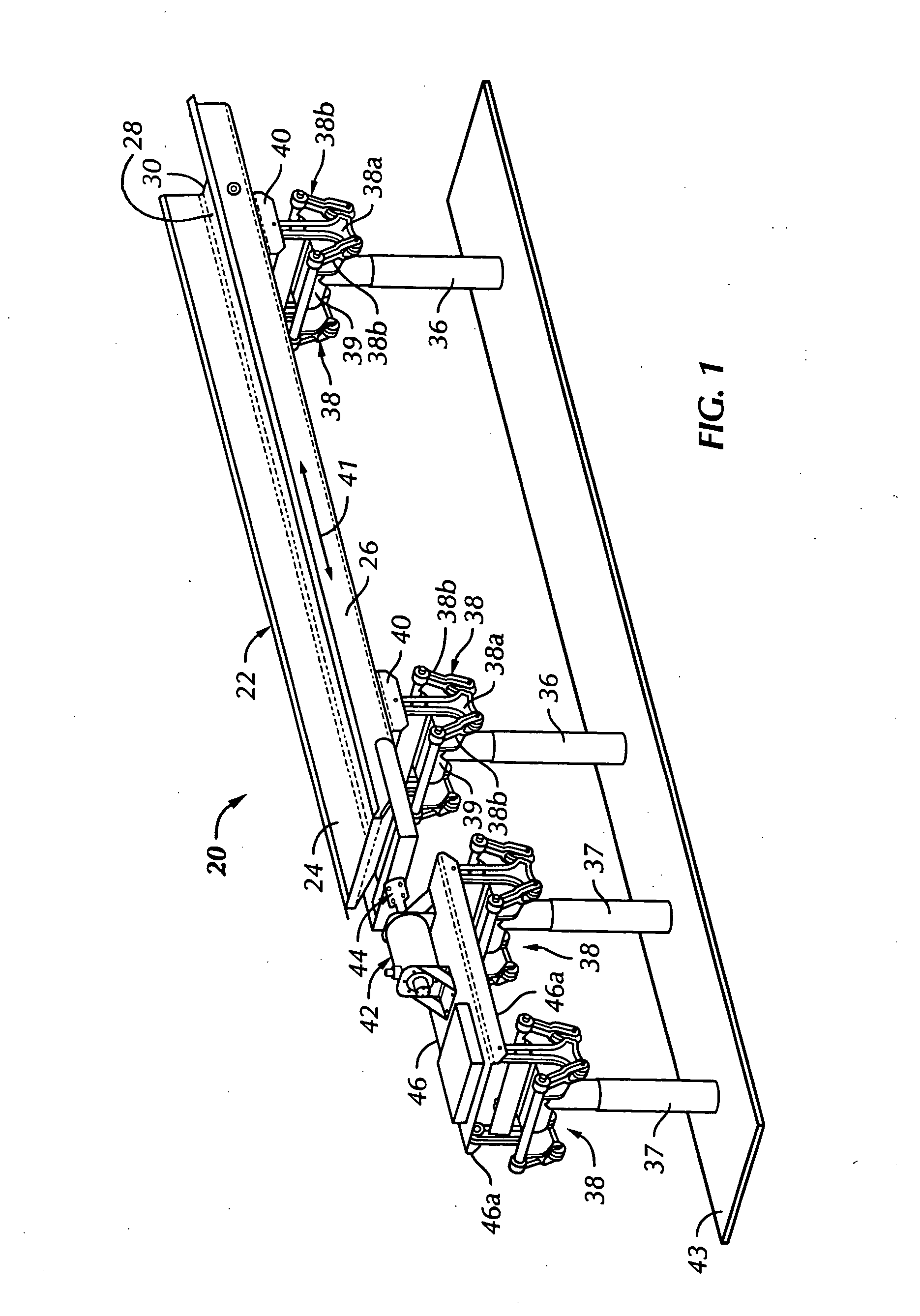
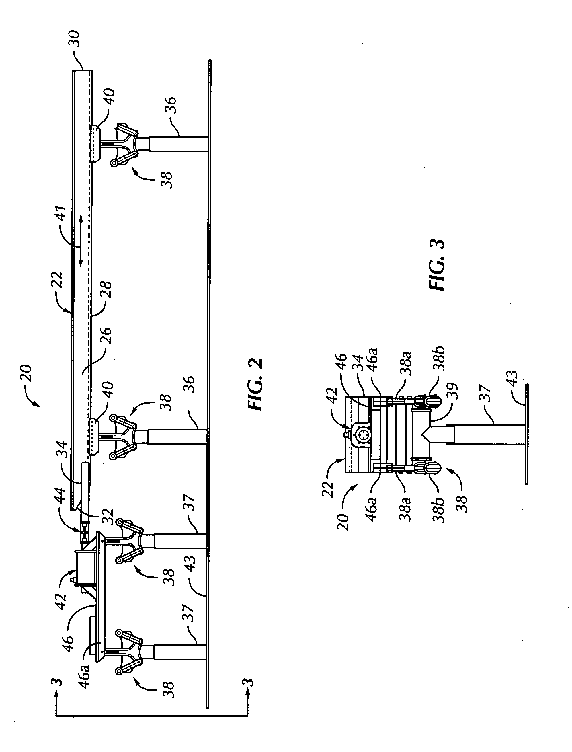
[0023] Referring now to FIGS. 1 through 3, there is illustrated one preferred embodiment of a substantially horizontal reciprocating conveyor system in accordance with the invention and generally designated by the numeral 20. The conveyor system 20 is characterized by an elongated, relatively shallow, channel shaped pan or tray member 22 comprising opposed sidewalls 24 and 26, a generally flat, horizontal bottom wall 28 and an open discharge end 30. The material inlet portion of the conveyor tray 22 includes a substantially closed end provided by a transverse wall 32. A somewhat yoke shaped actuator bracket member 34 is suitably connected to the tray 22 at the end having the closur...


PUM


Abstract

A linear reciprocating conveyor system includes an elongated tray connected to a linear electric motor, the tray and motor each being supported on linkages allowing linear reciprocating motion without transferring vibration to system support structure. The linear electric motor is adapted for control by a method which provides a current profile to effect reciprocation of the motor to convey articles or material with the tray in one direction and acceleration of the tray in the opposite direction to provide slippage of the material or articles, thus causing the material or articles to move toward a tray discharge end. The motor armature may be supported with respect to the motor stator by an air bearing system. Plural motors may be connected to the tray and also supported by an air bearing system.

Description

BACKGROUND OF THE INVENTION [0001] In the art of conveyor systems for transferring solid materials and articles, oscillating conveyors are known which are generally characterized as reciprocating conveyors and vibrating conveyors. Both types of conveyors of the general type use known components and apparatus which require frequent maintenance, due at least in part to the nature of the motion of the conveyor system and friction generated by the drive mechanism. [0002] Oscillating or reciprocating tray or pan conveyors are known which are driven by linear motors which attempt to initiate the conveying acceleration at a particular range of acceleration forces and then, during a further portion of a conveyance cycle, the acceleration increases to a value close to the so-called slip acceleration rate. Known types of linear motors are difficult to control to produce a high enough acceleration of the conveyor tray or pan on the slip portion of the cycle so as to easily exceed the coefficie...

Claims


Application Information

Patent Timeline
Patent Type & Authority Applications(United States)
IPC IPC(8): B65G27/00
CPCB65G27/12B65G27/08
Inventor HILLSTROM, KEVIN D.ZANETTI, JOHN M.BURGESS, RALPH D. JR.
Owner TRIPLES DYNAMICS
Learn More