Clinching method and tool for performing the same

a clinching method and tool technology, applied in the direction of manufacturing tools, soldering devices, auxillary welding devices, etc., can solve the problems of brittle phase formation, add manufacturing steps, process cost, thermal expansion of materials, etc., and achieve the effect of generating frictional hea

Active Publication Date: 2012-11-27
GM GLOBAL TECH OPERATIONS LLC
View PDF12 Cites 0 Cited by
  • Summary
  • Abstract
  • Description
  • Claims
  • Application Information

AI Technical Summary

Benefits of technology

[0003]A clinching method includes establishing a first layer on a second layer. The first layer has an aperture formed therein and is thinner than the second layer. A rotating punch is engaged with the second layer through the aperture in the first layer, thereby generating frictional heat and softening the second layer. The rotating punch is configured with at least a first diameter, a shoulder, and a second diameter that is larger than the first diameter. The rotating punch is pressed into the softened second layer, thereby causing at least some of the second layer to: back extrude through an annulus defined by the aperture in the first layer and at least one of the diameters of the punch; contact the shoulder of the rotating punch; and extend onto a surface of the first layer adjacent the aperture.

Problems solved by technology

Hot clinching techniques often result in the thermal expansion of the materials.
Friction stir spot welding often results in brittle phase formation when joining different materials (e.g., aluminum and magnesium).
The addition of an interlayer adds manufacturing steps and potentially cost to the process.
Other techniques may result in the splitting or cracking of the clinch button.

Method used


Image

  • Clinching method and tool for performing the same
  • Clinching method and tool for performing the same

Examples


Embodiment Construction

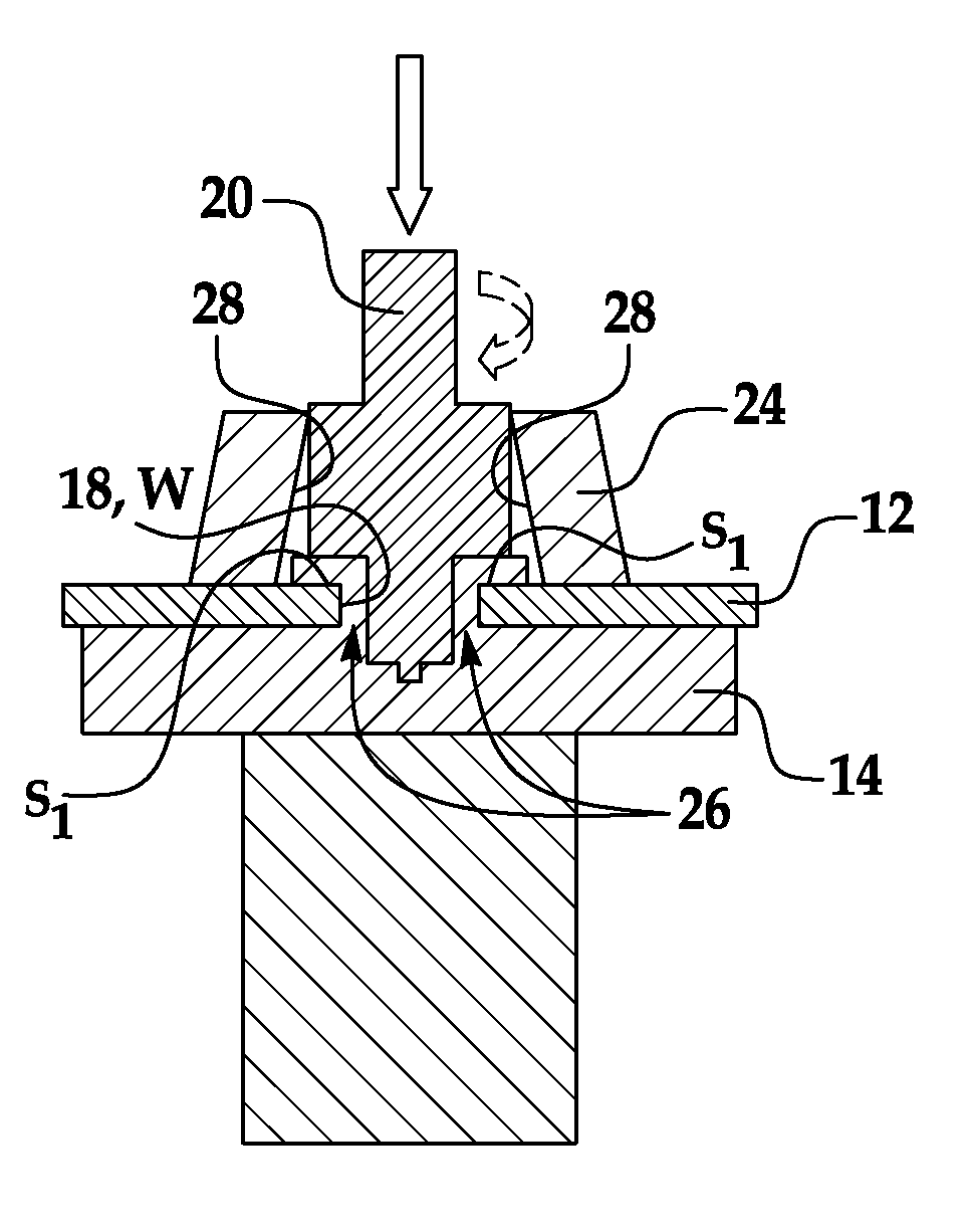
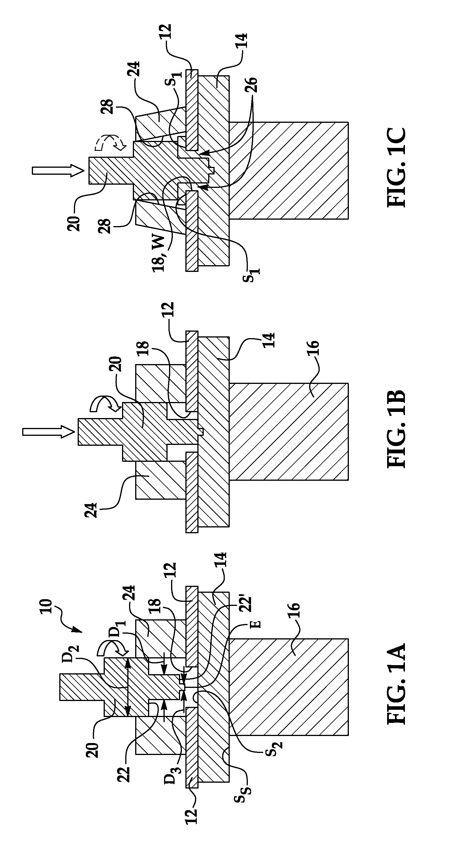
[0006]Embodiments of the clinching method disclosed herein advantageously form a mechanical joint between two materials by back extruding a softened material through an aperture formed in a material overlying the softened material. Alignment of the rotating punch with the aperture is simplified because the aperture is visible and accessible (compared to an aperture formed in the underlying material). Furthermore, friction stir spot welding of the two materials is not utilized to form a joint between the two materials, and additional rivets or other joining elements are not required to clinch the materials together.

[0007]Referring now to FIG. 1A, a schematic illustration of a clinching tool 10 is depicted having first and second layers 12, 14 secured therein. The tool 10 includes a support 16 which has a surface SS that receives and supports the layers 14, 12 during the operation of the tool 10. In a non-limiting example, the support 16 is made from hardened tool steel, has a 15 mm d...


PUM

PropertyMeasurementUnit
diameteraaaaaaaaaa
diameteraaaaaaaaaa
elongation at failureaaaaaaaaaa

Abstract

A clinching method includes establishing a first layer on a second layer. The first layer has an aperture formed therein and is thinner than the second layer. A rotating punch is engaged with the second layer through the aperture in the first layer, thereby generating frictional heat and softening the second layer. The rotating punch is configured with at least a first diameter, a shoulder, and a second diameter that is larger than the first diameter. The rotating punch is pressed into the softened second layer, thereby causing at least some of the second layer to: back extrude through an annulus defined by the aperture in the first layer and at least one of the diameters of the punch; contact the shoulder of the rotating punch; and extend onto a surface of the first layer adjacent the aperture.

Description

TECHNICAL FIELD[0001]The present disclosure relates generally to a clinching method and a tool for performing the same.BACKGROUND[0002]Materials may be secured together using many different methods, including, for example, hot clinching and friction stir spot welding. Hot clinching techniques often result in the thermal expansion of the materials. Friction stir spot welding often results in brittle phase formation when joining different materials (e.g., aluminum and magnesium). An attempt to decrease or prevent brittle phase formation in friction spot welding includes adding an interlayer to the materials to be joined. The addition of an interlayer adds manufacturing steps and potentially cost to the process. Other techniques may result in the splitting or cracking of the clinch button.SUMMARY[0003]A clinching method includes establishing a first layer on a second layer. The first layer has an aperture formed therein and is thinner than the second layer. A rotating punch is engaged ...

Claims


Application Information

Patent Timeline
Patent Type & Authority Patents(United States)
IPC IPC(8): B23K20/12
CPCB23K20/1255B23K20/126B23K20/1265B23K20/127B21J5/063B23K2203/08B23K2203/10B23K2203/18B23K2201/18B23K2101/18B23K2103/08B23K2103/10B23K2103/15B23K2103/18
Inventor CARTER, JON T.
Owner GM GLOBAL TECH OPERATIONS LLC
Why Eureka
Try Eureka