Apparatus and method of separating and concentrating organic and/or non-organic material

a technology of organic and non-organic materials, applied in the direction of gas current separation, lighting and heating apparatus, furnaces, etc., can solve the problems of not being able to separate coal particles containing organic sulfur from coal particles largely free of sulfur, affecting the quality of the separation process, and affecting the separation effect of organic and/or non-organic materials, so as to reduce the amount of contaminated particulates, increase the amount of usable non-contaminated, and process evenly and quickly

Active Publication Date: 2007-08-23
RAINBOW ENERGY CENT LLC
View PDF99 Cites 7 Cited by
  • Summary
  • Abstract
  • Description
  • Claims
  • Application Information

AI Technical Summary

Benefits of technology

[0015] One advantage of the present invention is that it permits generally continuous processing of the particulate. As the non-fluidized particulate is conveyed from the fluidized bed to the collector box more particulate can be added for processing.
[0016] Another advantage of the present invention is a generally horizontal conveyance of the non-particulate. The generally horizontal conveyance of the non-fluidized particulate ensures that all of the particulate is processed evenly and quickly by mixing or churning the material while it is being conveyed.
[0017] Still yet another advantage of the present invention is that it includes a second fluidizing step or apparatus to capture more non-contaminated fluidizable particulates that are still trapped, or have become trapped, in the non-fluidized particulate. Capturing more of the fluidized particulate increases the amount of usable non-contaminated particulates, while reducing the amount of contaminated particulates that will be subject to further processing or disposal. By capturing more of the usable non-contaminated particulates and reducing the amount of contaminated particulate a company is able to increase its efficiency while reducing its costs.

Problems solved by technology

However, they also contain medium to high levels of sulfur.
As a result of increasingly stringent environmental regulations like the Clean Air Act in the U.S., electric power plants have had to install costly scrubber devices in the smokestacks of these plants to prevent the sulfur dioxide (“SO2”), nitrous oxides (“NOx”), and fly ash that result from burning these coals to pollute the air.
However, they still produce sufficient levels of SO2, NOx, and fly ash when burned such that treatment of the flue gas is required to comply with federal and state pollution standards.
Such processes may work readily to separate nuts, bolts, racks, etc. from coal, however, they would not be expected to separate coal particles containing organic sulfur from coal particles largely free of sulfur since the specific gravities of these two coal fractions can be relatively close.
However, utilization of carbon sorben-based serubber devices can be very expensive to install and operate.
Moreover, currently existing emissions control equipment can work less well for high-rank coals (anthracite and bituminous) vs. low-rank coals (subbitumionous and lignite).
However, this pre-combustion thermal pretreatment process is still capital intensive in that it requires a dual zone reactor to effectuate the drying and mercury volatilization steps.
Furthermore, 20-30% of the mercury cannot be removed from the coal by this process, because it is tightly bound to the carbon contained in the coal.
Thus, the expensive scrubber technology will still be required to treat flue gas resulting from combustion of coal pretreated by this method because of the appreciable levels of mercury remaining in the coal after completion of this thermal pre-treatment process.

Method used


Image

  • Apparatus and method of separating and concentrating organic and/or non-organic material
  • Apparatus and method of separating and concentrating organic and/or non-organic material
  • Apparatus and method of separating and concentrating organic and/or non-organic material

Examples


Embodiment Construction

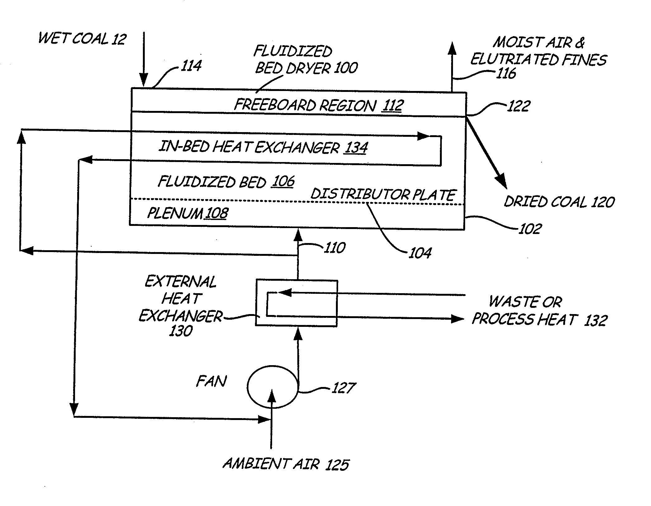
[0043] The invention includes an apparatus for, and a method of, separating particulate from denser and / or larger particulate containing contaminants or other undesirable constituents, while concentrating the denser and / or larger material and contaminants for removal and / or further processing. The method of separation utilized in the present invention capitalizes on the physical characteristics of the contaminants. In particular, it capitalizes on the difference between the specific gravity of contaminated and non-contaminated material. The contaminants can be removed from a majority of the material by separating and removing the denser and / or larger material. The present invention uses a fluidization method of separating the contaminated denser and / or larger material from the non-contaminated material.

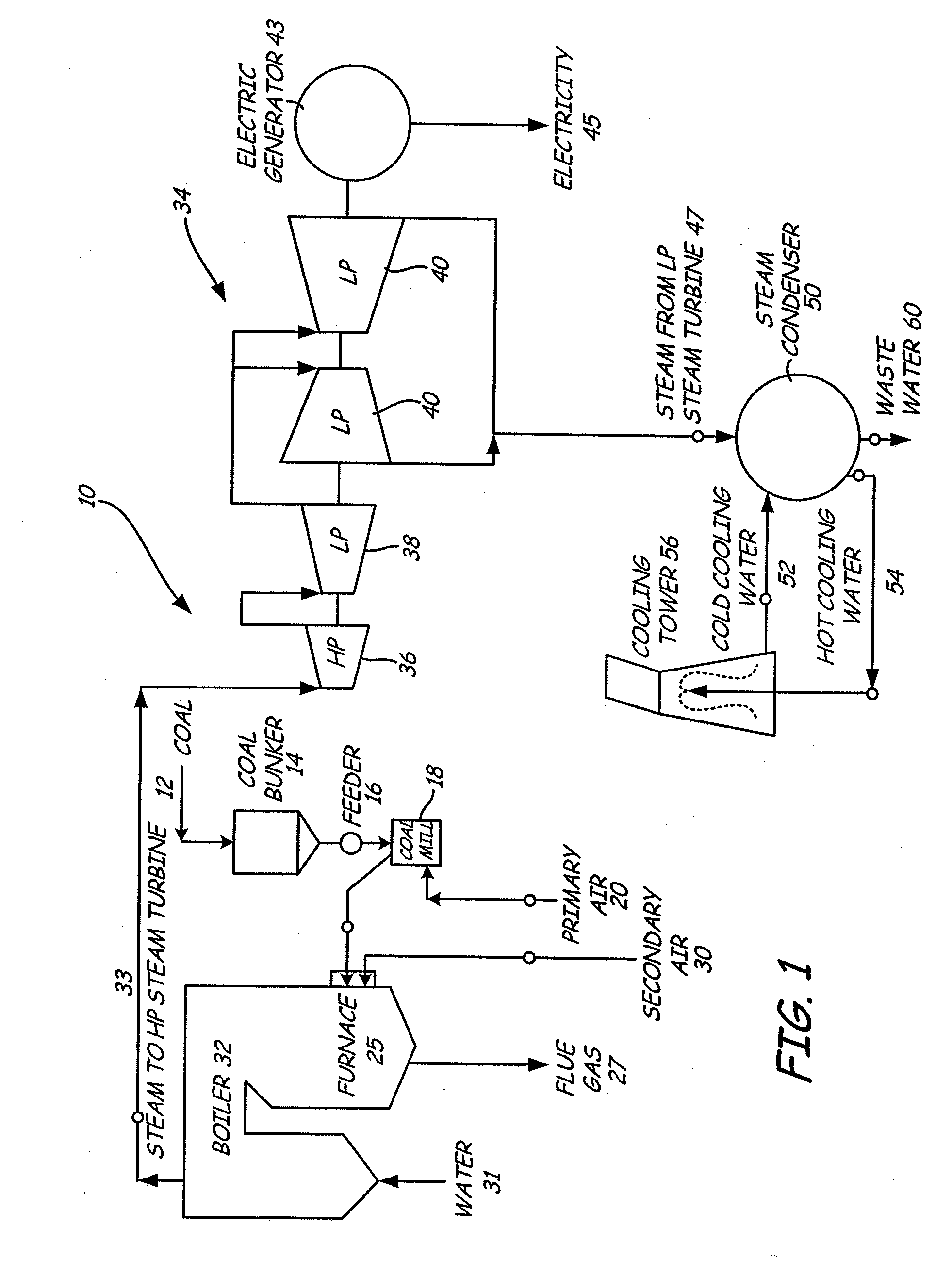
[0044] Although the present invention may be used in a variety of applications such as in farming, and / or manufacturing, the following discussion will describe its use in power plant...


PUM


Abstract

An apparatus for segregating particulate by density and / or size including a fluidizing bed having a particulate receiving inlet for receiving particulate to be fluidized. The fluidized bed also includes an opening for receiving a first fluidizing stream, an exit for fluidized particulate and at least one exit for non-fluidized particulate. A conveyor is operatively disposed in the fluidized bed for conveying the non-fluidized particulate to the non-fluidized particulate exit. A collector box is in operative communication with the fluidized bed to receive the non-fluidized particulate. There is a means for directing a second fluidizing stream through the non-fluidized particulate as while it is in the collector box to separate fluidizable particulate therefrom.

Description

CROSS-REFERENCE TO RELATED APPLICATION [0001] This application is a continuation of U.S. patent application Ser. No. 11 / 107,153 filed on Apr. 15, 2005, which claims the benefit of U.S. provisional application Ser. No. 60 / 618,379 filed on Oct. 12, 2004, which are hereby incorporated in their entirety by reference.FIELD OF THE INVENTION [0002] This invention relates to an apparatus for and method of separating particulate material from denser and / or larger material containing contaminants or other undesirable constituents, while concentrating the denser and / or larger material for removal and further processing or disposal. More specifically, the invention utilizes a scrubber assembly in operative communication with a fluidized bed that is used to process coal or another organic material in such a manner that the denser and / or larger material containing contaminates or other undesirable constituent is separated from the rest of the coal or other organic material. BACKGROUND OF THE INVE...

Claims


Application Information

Patent Timeline
Patent Type & Authority Applications(United States)
IPC IPC(8): B07B4/00B07B7/00
CPCB03B4/06C10B57/10F26B3/084F23K2201/20F23K2201/30F23K1/04Y02P20/129
Inventor NESS, MARK A.COUGHLIN, MATTHEW P.
Owner RAINBOW ENERGY CENT LLC
Why Eureka
Try Eureka