White-Light Emitting Device, and Phosphor and Method of Its Manufacture

a technology of white light and phosphor, which is applied in the direction of discharge tube luminescnet screens, condensed vapors, sustainable buildings, etc., can solve the problems of short lifespan, inability to synthesize white light of a color temperature of choice, and prohibitive white light synthesizing, etc., to achieve high light-emitting efficiency, improve emission efficiency and temperature stability, and improve the effect of temperature stability

Inactive Publication Date: 2007-08-23
SUMITOMO ELECTRIC IND LTD
View PDF5 Cites 2 Cited by
  • Summary
  • Abstract
  • Description
  • Claims
  • Application Information

AI Technical Summary

Benefits of technology

[0010] An object of the present invention is by utilizing phosphors of superior temperature characteristics and high light-emitting efficiency to afford a white-light emitting device that exce...

Problems solved by technology

Nevertheless, a drawback with ZnSe LEDs is that they have a short lifespan because they are prone to deterioration.
This means that white light of a color temperature of choice cannot be synthesized, and in particular is prohibitive of synthesizing white light of color temperature lower than the proximity of 5000 K. In general, because the color temperature of white electric-light bulbs is a low 3500 K or thereabouts, with InGaN white-light emitting devices white light of the same color temperature as with white light bulbs cannot be realized and only white light of color temperature differing from that of white light bulbs is feasible.
Consequently, white light bulb replacements by means of InGaN white-light emitting devices, despite having superior lifespan and efficie...

Method used


Image

  • White-Light Emitting Device, and Phosphor and Method of Its Manufacture
  • White-Light Emitting Device, and Phosphor and Method of Its Manufacture
  • White-Light Emitting Device, and Phosphor and Method of Its Manufacture

Examples


embodiments

Embodiment 1

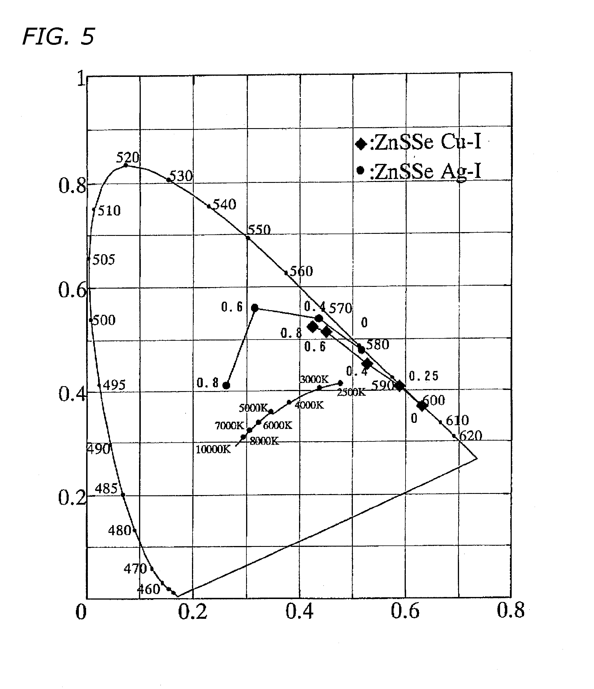
[0076] The white-light emitting device depicted in FIG. 9 was prepared. At first a ZnSSe crystal was grown using the iodine transport method and subsequently underwent heat treatment within a 1000° C. atmosphere in which Zn and Cu vapors were mixed, whereby a ZnS0.6Se0.4 crystal of predetermined composition (ZnS atomic fraction 0.6) was prepared. This phosphor corresponds to the rhombic mark for ZnS atomic fraction 0.6 nearby wavelength 570 nm on the chromaticity diagram, and is a yellow-light emitting phosphor. A ZnSSe plate of 250 microns thickness was cut out from the ZnS0.6Se0.4 crystal. Both sides of the ZnSSe plate were polished to a mirror-like finish, bringing the thickness down to 200 μm, and the polished plate was sliced into a 3 mm square to produce a ZnS0.6Se0.4 phosphor plate.

[0077] In addition, a blue LED chip of 450 nm emission wavelength, having an InGaN active layer, was readied. An Ag paste was employed to bond the LED chip onto a chip die (lead-frame...

embodiment 2

[0078] The white-light emitting device depicted in FIG. 10 was prepared. AZnSSe plate of 250 microns thickness was cut out from a ZnS0.6Se0.4 crystal (ZnS atomic fraction 0.6) at first being grown using the iodine transport method, and subsequently undergoing heat treatment within a 1000° C. atmosphere in which Zn and Ag vapors were mixed. This phosphor corresponds to the black-dot mark for ZnS atomic fraction 0.6 on the chromaticity diagram, and is a green-light emitting phosphor. Both sides of the ZnSSe plate were polished to a mirror-like finish, bringing the thickness down to 200 microns, and the polished plate was sliced into a 3 mm square to produce a ZnSSe phosphor plate (green phosphor: first phosphor).

[0079] In addition, a 400-micron square, 250-micron thick ZnS0.25Se0.75 phosphor plate (red phosphor: second phosphor) was prepared from a ZnS0.25Se0.75 crystal (ZnS atomic fraction 0.25) that was grown using the iodine transport method and subsequently underwent heat treatme...


PUM


Abstract

White-light emitting device that excels in emission efficiency and temperature stability and that can put out white light of a color temperature of choice is afforded by utilizing phosphors of superior temperature characteristics and high light-emitting efficiency; the phosphors and a method of manufacturing the phosphors are also made available. An LED (1), and a phosphor (3) ZnSxSe1−x (0<x<1) that contains at least one activator among Cu, Ag and Au and that, excited by light irradiated from the LED, produces light are furnished.

Description

BACKGROUND OF THE INVENTION [0001] 1. Technical Field [0002] The present invention relates to white-light emitting devices, phosphors utilized in the devices, and to methods of manufacturing the phosphors. [0003] 2. Description of the Related Art [0004] Reference is made to FIG. 11, a view depicting an example of a conventional white-light emitting device. (See for example Optically Active Materials Manual Managing Editorial Group, Eds., “Optically Active Materials Manual,” The Optronics Co., Ltd., June 1997.) In FIG. 11, surrounding an InGaAs blue LED 101 disposed in the mounting portion 109 of a lead frame is an encompassing synthetic-polymer casting 106 in which a YAG (yttrium-aluminum-garnet) phosphor is dispersed. A molded synthetic-polymer seal 116 seals the casting 106, metal wires 105, and the lead frame. Through the wires 105 out of separated respective portions of the lead frame, voltage is applied across two electrodes 107a and 107b, and current flows into the blue LED 10...

Claims


Application Information

Patent Timeline
IPC IPC(8): C09K11/54C09K11/56C09K11/08C01B25/02C09K11/62C09K11/88H01J1/62H01L33/32H01L33/50H05B33/14
CPCC09K11/883H01L33/502C30B23/00C30B29/48H01L2224/48091H01L2224/48247H01L2224/48257H01L2924/16195H01L2224/45144Y02B20/00H01L2924/00014H01L2924/00
Inventor FUJIWARA, SHINSUKE
Owner SUMITOMO ELECTRIC IND LTD
Why Eureka
Try Eureka