System and method for providing power to an electronic device

a technology of electronic devices and systems, applied in the field of electronic systems, can solve the problems of not making their power cord units compatible with the electronic devices of other manufacturers or other types of electronic devices, the battery connector made by one manufacturer typically does not fit into the battery power receptacle made by another manufacturer, and the battery connector made for one type of device typically does not fit into the battery power receptacle made for another type of devi

Inactive Publication Date: 2007-08-23
FLI CHARGE LLC
View PDF59 Cites 45 Cited by
  • Summary
  • Abstract
  • Description
  • Claims
  • Application Information

AI Technical Summary

Benefits of technology

[0008] The present invention employs an electronic system having a power delivery support structure with a power delivery surface. The power delivery surface is defined by separate conductive regions which can provide a potential difference between them. The invention also employs an electronic device having a plurality of contacts arranged so at least one of them engages one of the conductive regions and another of them engages another of the conductive regions when the electronic device is carried by the power delivery support structure. The power delivery surface and contacts are arranged so the potential difference is provided to the contacts independently of the orientation of the electronic device relative to the power delivery surface. The electronic device includes and carries a circuit which receives the potential difference from the contacts, rectifies it and provides a desired potential difference which is used to power the electronic device.

Problems solved by technology

Manufacturers, however, generally make their own model of electronic device and do not make their power cord unit compatible with the electronic devices of other manufacturers or with other types of electronic devices.
As a result, a battery connector made by one manufacturer will typically not fit into the battery power receptacle made by another manufacturer.
Further, a battery connector made for one type of device typically will not fit into the battery power receptacle made for another type of device.
This can be a problem for the consumer because he or she has to buy a compatible power cord unit for their particular electronic device.
Since people tend to switch devices often, it is inconvenient and expensive for them to also have to switch power cord units.
Further, power cord units that are no longer useful are often discarded which leads to waste.
Also, people generally own a number of different types of electronic devices and owning a power cord unit for each one is inconvenient.

Method used


Image

  • System and method for providing power to an electronic device
  • System and method for providing power to an electronic device
  • System and method for providing power to an electronic device

Examples


Embodiment Construction

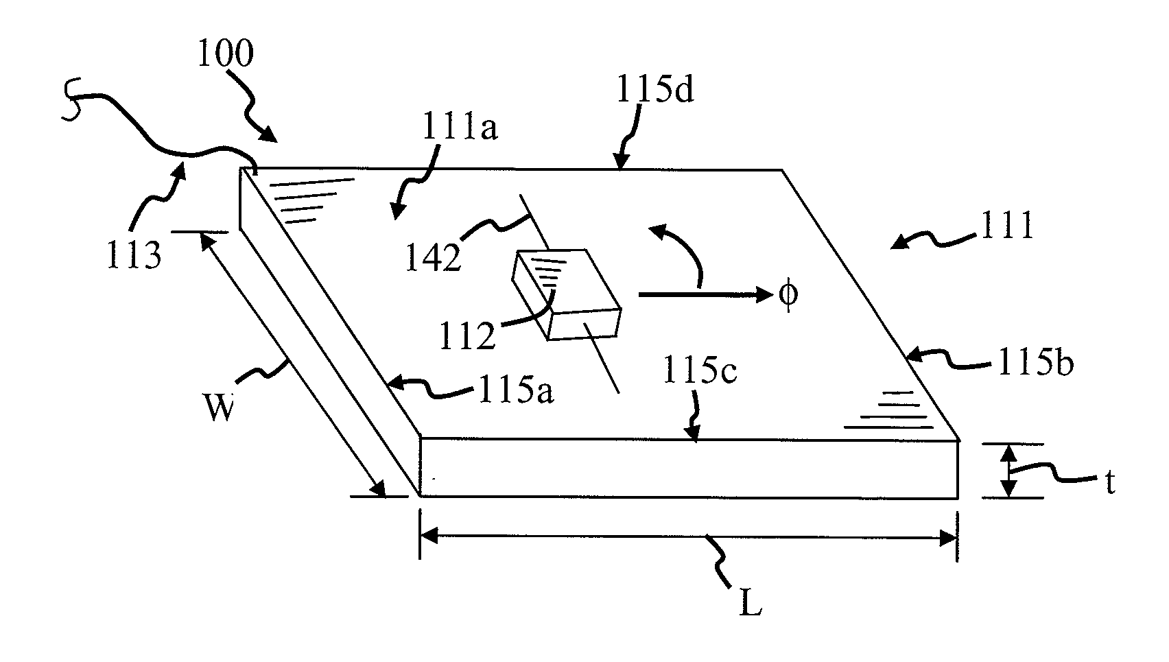
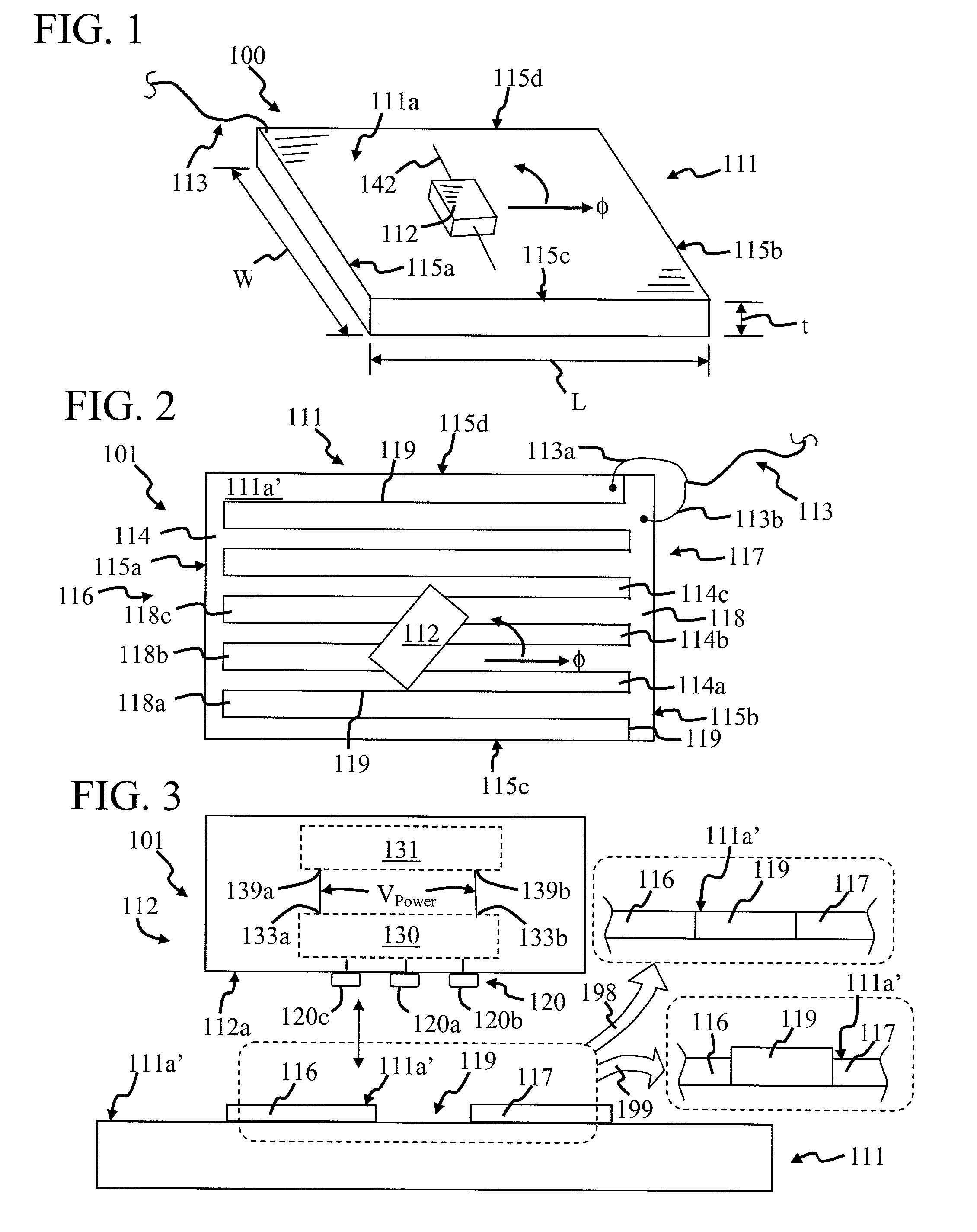
[0052]FIG. 1 is a perspective view of a power delivery system 100, in accordance with the invention, for providing power to an electrical or electronic device 112 with a power delivery surface 111a. Power delivery system 100 can power more than one electronic device made by the same or different manufacturers. It can also power different types of electronic devices. This reduces the need for the consumer to have a power cord unit for each electronic device they use. Electronic device 112 can be of many different types, such as a toys, game devices, cell phone, laptop computer, camera, personal digital assistant, etc. Most of these devices are mobile and powered by a rechargeable battery. However, the invention is also applicable to electronic devices, such as a desktop computer, that are not generally considered to be mobile.

[0053] System 100 includes a power delivery support structure 111 connected to a power source (not shown) through a power cord unit 113. The power source can b...


PUM


Abstract

An electronic system includes a power delivery support structure having a power delivery surface with first and second conductive regions. An electronic device includes a plurality of contacts arranged so at least one of them engages the first conductive region and at least another of them engages the second conductive region independently of the orientation of the device relative to the power delivery surface.

Description

CROSS-REFERENCES TO RELATED APPLICATIONS [0001] The present application is a continuation-in-part of U.S. patent application Ser. No. 10 / 732,103 filed on Dec. 10, 2003, which claims the benefit of U.S. Provisional Application Ser. Nos. 60 / 432,072, 60 / 441,794 and 60 / 444,826, filed on Dec. 10, 2002, Jan. 22, 2003 and Feb. 4, 2003, respectively, all of which are incorporated herein by reference. The present application also claims priority to U.S. Provisional Application Ser. Nos. 60 / 776,332, 60,778,761, 60 / 781,456 and 60 / 797,140 filed on Feb. 24, 2006, Mar. 3, 2006, Mar. 10, 2006 and May 3, 2006, respectively, all of which are incorporated herein by reference.BACKGROUND OF THE INVENTION [0002] 1. Field of the Invention [0003] The present invention relates to electronic systems and methods for providing electrical power to one or more electronic devices through a power delivery surface. [0004] 2. Description of the Related Art [0005] A variety of mobile electronic devices, such as toys...

Claims


Application Information

Patent Timeline
Patent Type & Authority Applications(United States)
IPC IPC(8): A63F3/00
CPCG06F1/1626G06F1/1632G06F1/1635G06F1/1656G06F1/181H04M1/0262G06F1/266H01R13/22H01R25/147H02J7/0045G06F1/26
Inventor RANDALL, MITCH
Owner FLI CHARGE LLC
Why Eureka
Try Eureka