Motor and electrical appliance provided with same

a technology of electric motors and electrical appliances, which is applied in the direction of rotating magnets, magnetic circuit rotating parts, synchronous machines with stationary armatures, etc., can solve the problems of abnormal sound, unnecessary high-frequency signals likely to radiate from brushless motors, electrolytic corrosion inside bearings, etc., and suppress the voltage generated in two bearings. , the effect of suppressing electrolytic corrosion

Active Publication Date: 2013-05-16
PANASONIC CORP
View PDF11 Cites 19 Cited by
  • Summary
  • Abstract
  • Description
  • Claims
  • Application Information

AI Technical Summary

Benefits of technology

[0046]As described above, in the electric motor of the present invention, the shaft voltage generated in two bearings can be suppressed low. Thus, an electric motor with suppressed electrolytic corrosion and an electric device including the electric motor can be provided.

Problems solved by technology

On the other hand, the PWM system performs switching using high-frequency pulses, and thus unnecessary high-frequency signals are likely to radiate from the brushless motor.
When the shaft voltage reaches the dielectric breakdown voltage of the oil film inside the bearing, micro-current flows inside the bearing and causes electrolytic corrosion inside the bearing.
When the electrolytic corrosion proceeds, a wavy abrasion phenomenon can occur on the bearing inner ring, the bearing outer ring, or bearing balls, which leads to abnormal sound.
This is one of the major factors of failures in the electric motor.
In this manner, electric motors using the PWM system are likely to generate unnecessary high-frequency signals that cause noise, and such unnecessary electromagnetic radiation causes electrolytic corrosion in the bearing.
However, the conductive lubricant has conductivity deteriorated with a lapse of time, and lacks sliding reliability.
However, this method produces brush abrasion powder and requires space.
This method is highly effective in suppressing electrolytic corrosion, but requires high cost.
Thus, this method cannot be used for general-purpose electric motors.
That is, generally, in the electric motor that is used in a washing machine, a dish washer / dryer, or the like, installed in a wet place and thus can cause electric shock, independent insulation (hereinafter, referred to as additional insulation) needs to be added to the insulation in the live part (basic insulation).
In this case, impedances cause a difference in voltage drop.
This unbalanced state can produce a high shaft voltage.
Such a high shaft voltage can cause electrolytic corrosion in the bearing.
As described above, also the structure of the brushless motor itself is likely to unbalance the impedance of the rotor side and that of the stator side.
This generates an electric potential difference, i.e. a shaft voltage, between the inner ring and the outer ring of the bearing, which causes electrolytic corrosion in the bearing.
However, since such a molding material is made of resin, its strength is not sufficiently high to fix the bearing.
Further, the resin molding provides low dimensional accuracy, which is likely to cause creep failures in the bearing.
When such force is generated, the relative difference in the radial direction is likely to cause a sliding phenomenon.
That is, inversely, the shaft voltage is increased and electrolytic corrosion is more likely to occur.
Thus, large capacitance is likely to be generated between the heat exchanger and the fan.
Thus, in the case of such an air conditioner, the effect of this capacitance can unbalance the impedance in the electric motor with high possibility.
This causes different shaft voltages in the two bearings and can cause a failure such that one bearing has no electrolytic corrosion but the other bearing has electrolytic corrosion.

Method used


Image

  • Motor and electrical appliance provided with same
  • Motor and electrical appliance provided with same
  • Motor and electrical appliance provided with same

Examples


first exemplary embodiment

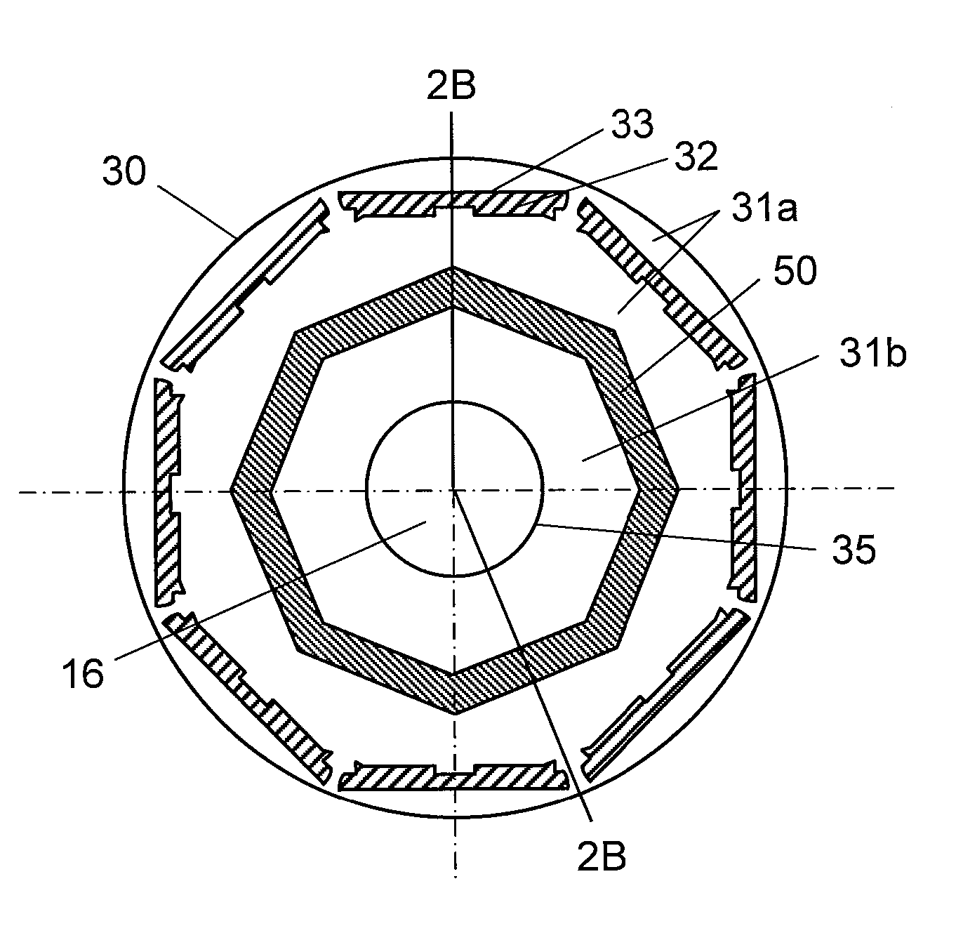
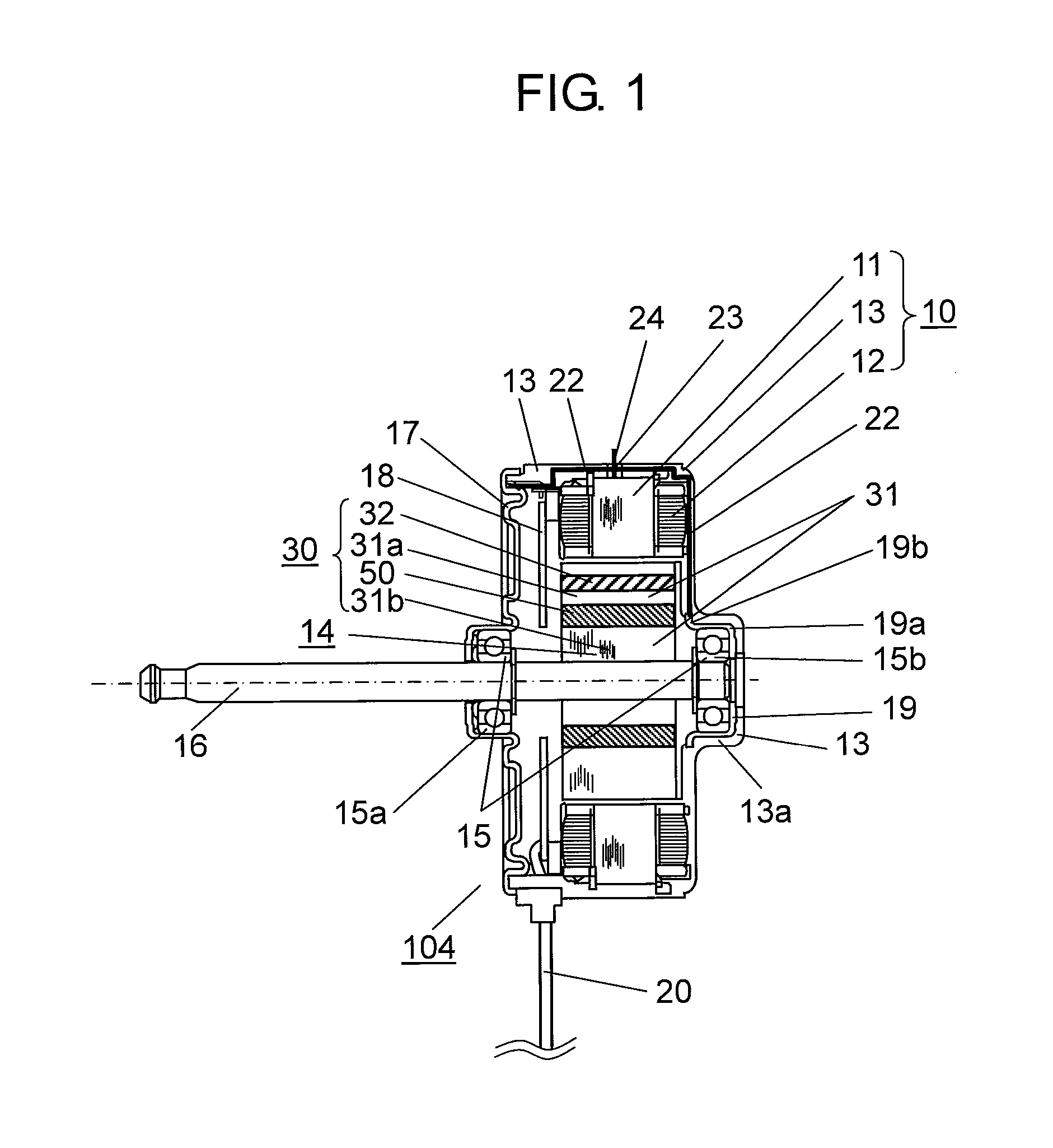
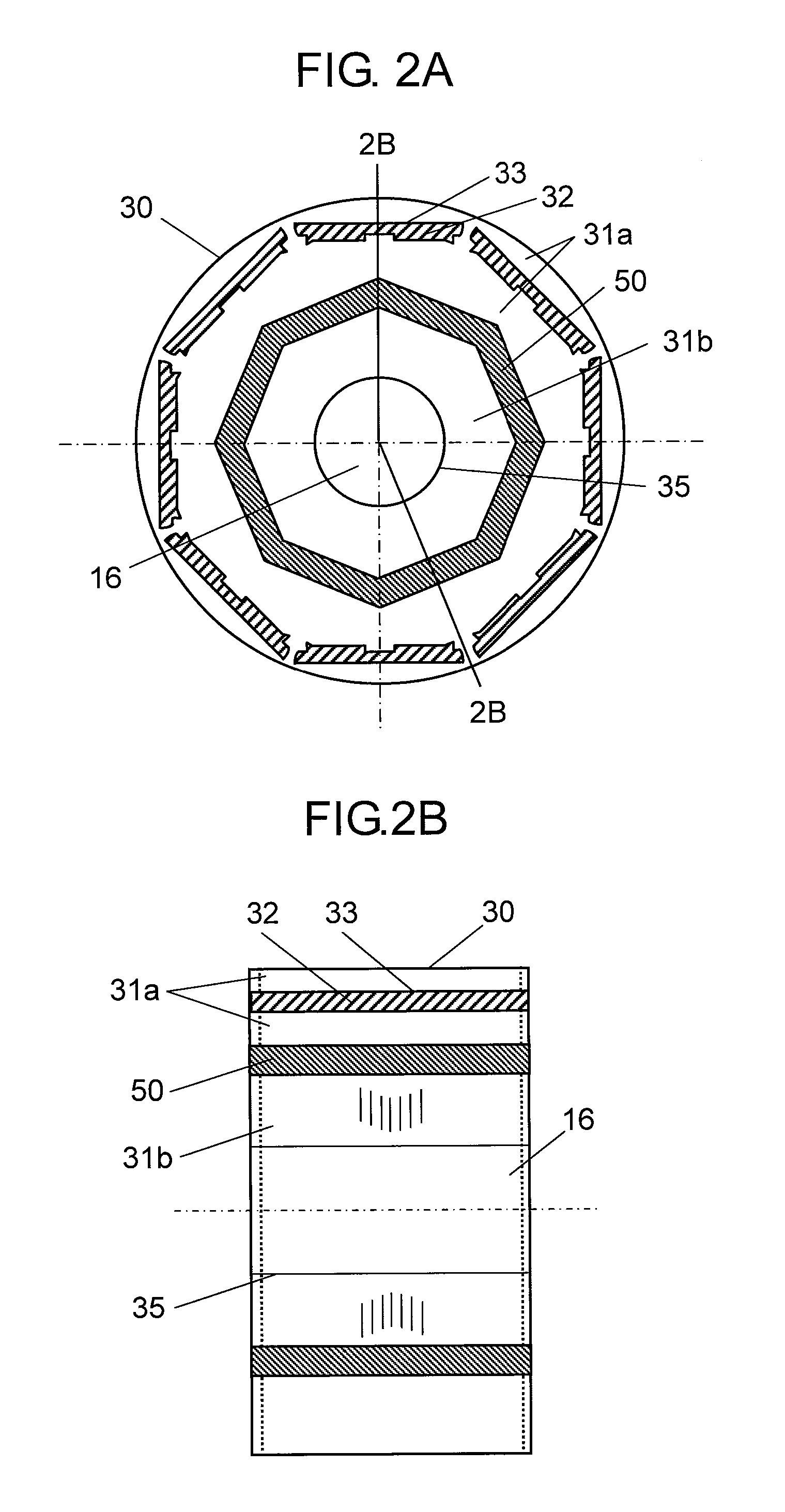
[0054]FIG. 1 is a structural diagram showing a section of electric motor 104 in accordance with the first exemplary embodiment of the present invention. In this exemplary embodiment, a description is provided for an example of a brushless motor using the PWM system, as electric motor 104. In this exemplary embodiment, as an example, a description is provided for an inner-rotor type brushless motor, where a rotor is disposed rotatably on the inner circumferential side of a stator.

[0055]With reference to FIG. 1, stator winding 12 is wound on stator iron core 11 with an insulator interposed between the stator iron core and the winding. Stator winding 12 is driven by an inverter of the pulse width modulation system. Such stator iron core 11 is molded with insulating resin 13, as a molding material, together with other fixing members. In this exemplary embodiment, these members are integrally molded in this manner so as to form stator 10 having a substantially cylindrical contour.

[0056]O...

second exemplary embodiment

[0082]FIG. 4 is a configuration diagram of an air conditioner in accordance with the second exemplary embodiment of the present invention. In this exemplary embodiment, an air conditioner installed indoors as an indoor unit is described as an example of an electric device of the present invention. As shown in FIG. 4, air conditioner 100 includes heat exchanger 102, fan 103, and electric motor 104 of the first exemplary embodiment in housing 101.

[0083]Heat exchanger 102 is configured so as to include a conductive metal member, and performs heat exchange of the air having taken in from a suction part for cooling and heating. Fan 103 is a cross flow fan, and blows the air conditioned by heat exchanger 102. Electric motor 104 is connected to fan 103 via rotating shaft 16 of electric motor 104, and rotary-drives fan 103. With such a configuration of air conditioner 100, the air conditioned by heat exchanger 102 is blown by rotation of fan 103 into the room, for example.

[0084]As described...

third exemplary embodiment

[0086]Next, a detailed description is provided for a configuration of an outdoor unit of an air conditioner in accordance with the third exemplary embodiment as another example of an electric device of the present invention.

[0087]With reference to FIG. 5, air conditioner outdoor unit 301 includes electric motor 104 of the first exemplary embodiment inside housing 311. Electric motor 104 has fan 312 attached to rotating shaft 16, and functions as a blower electric motor.

[0088]Air conditioner outdoor unit 301 is partitioned into compressor chamber 306 and heat-exchanger chamber 309 by partition plate 304 standing on base plate 302 of housing 311. Compressor 305 is disposed in compressor chamber 306. Heat exchanger 307 and the blower electric motor are disposed in heat-exchanger chamber 309. Electrical component box 310 is disposed on partition plate 304.

[0089]In the blower electric motor, fan 312 is rotated by rotation of electric motor 104 that is driven by motor drive unit 303 house...


PUM


Abstract

An electric motor includes a stator that has a stator winding wound on a stator iron core; a rotor having a rotating body with a rotating shaft in the center; a bearing for journaling the rotating shaft; and two conductive brackets for fixing the bearing. The rotating body holds a magnet such that the magnet faces the stator, and is fastened to the rotating shaft penetrating through the center of the rotating body. In the rotating body, a dielectric layer is formed between the rotating shaft and the outer circumference of the rotating body. The dielectric layer has a polygonal shape with the rotating shaft in the center. An electric device includes the thus configured electric motor.

Description

TECHNICAL FIELD[0001]The present invention relates to an electric motor and an electric device including the electric motor, and particularly to an electric motor and an electric device including the electric motor improved to suppress occurrence of electrolytic corrosion in the bearing of the electric motor.BACKGROUND ART[0002]An air conditioner for air conditioning, such as cooling and heating, as one of electric devices, generally includes a fan for blowing air and an electric motor for rotary-driving the fan. In recent years, so-called brushless motors have been used as electric motors in many cases. In such a brushless motor, an inverter of a pulse width modulation system (hereinafter, referred to as a PWM system as appropriate) is used. On the other hand, the PWM system performs switching using high-frequency pulses, and thus unnecessary high-frequency signals are likely to radiate from the brushless motor.[0003]In order to address this problem, an air conditioner for reducing...

Claims


Application Information

Patent Timeline
Patent Type & Authority Applications(United States)
IPC IPC(8): H02K1/27
CPCH02K5/1732H02K1/276H02K1/27H02K11/0089H02K11/40
Inventor WATANABE, AKIHIKOISOMURA, YOSHINORIMAETANI, TATSUOSATO, HIROKI
Owner PANASONIC CORP
Why Eureka
Try Eureka