Permanent current switch

a permanent current switch and current current technology, applied in the direction of superconducting magnets/coils, magnetic bodies, magnetic materials, etc., can solve the problem of inability to prepare resistance values, and achieve high reliability, thermal stability, and high temperature margin

Inactive Publication Date: 2007-08-23
HITACHI LTD
View PDF0 Cites 11 Cited by
  • Summary
  • Abstract
  • Description
  • Claims
  • Application Information

AI Technical Summary

Benefits of technology

[0018]In addition, according to a predetermined embodiment, it is possible to provide a highly reliable permanent current switch which allows a magnetic field to decay.
[0019]According to the present invention, there can be provided a permanent current switch which has a high temperature margin and which is thermally stable and which can securely perform an operation of switching a superconducting wire between a superconducting state and a normal conducting state.

Problems solved by technology

However, there has been a problem that even if the permanent current switch is prepared simply using the MgB2 wire, the switch has a resistance of about 1×10⁻¹⁰Ω, and a highly reliable permanent current switch having a less resistance value cannot be prepared.

Method used


Image

  • Permanent current switch
  • Permanent current switch
  • Permanent current switch

Examples


example 1

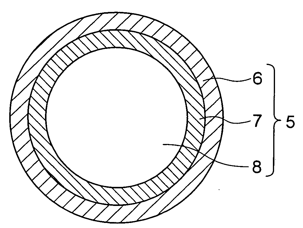
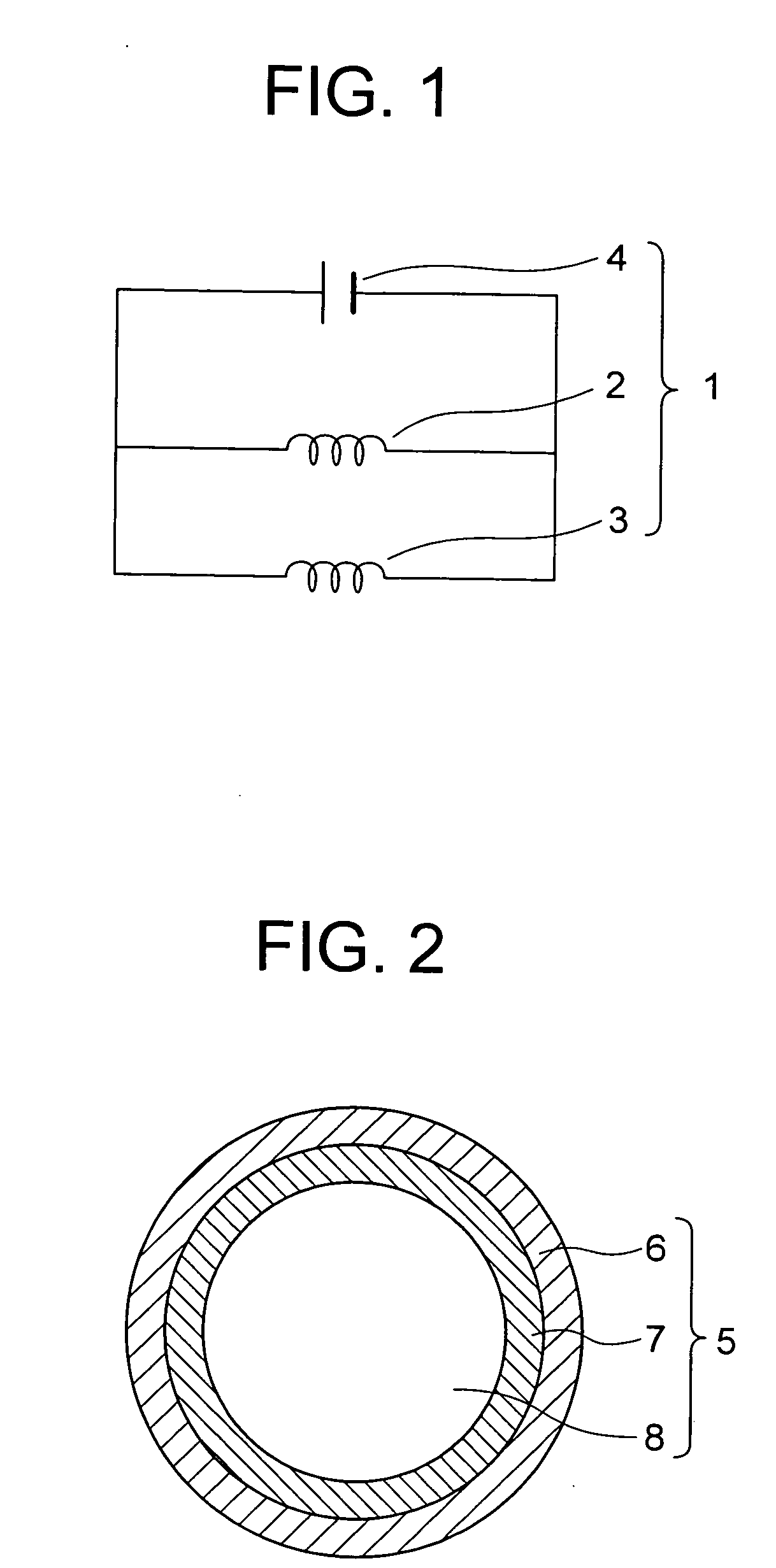
[0042]FIG. 2 shows a sectional structure of a magnesium diboride superconducting wire (an MgB2 wire) in the present embodiment.

[0043]An MgB2 wire 5 is constituted of a high-resistance metal 6, a superconducting metal 7, and a magnesium diboride superconducting portion (an MgB2 portion) 8. It is to be noted that the MgB2 wire 5 preferably has a diameter of about 0.3 mm to 2.5 mm.

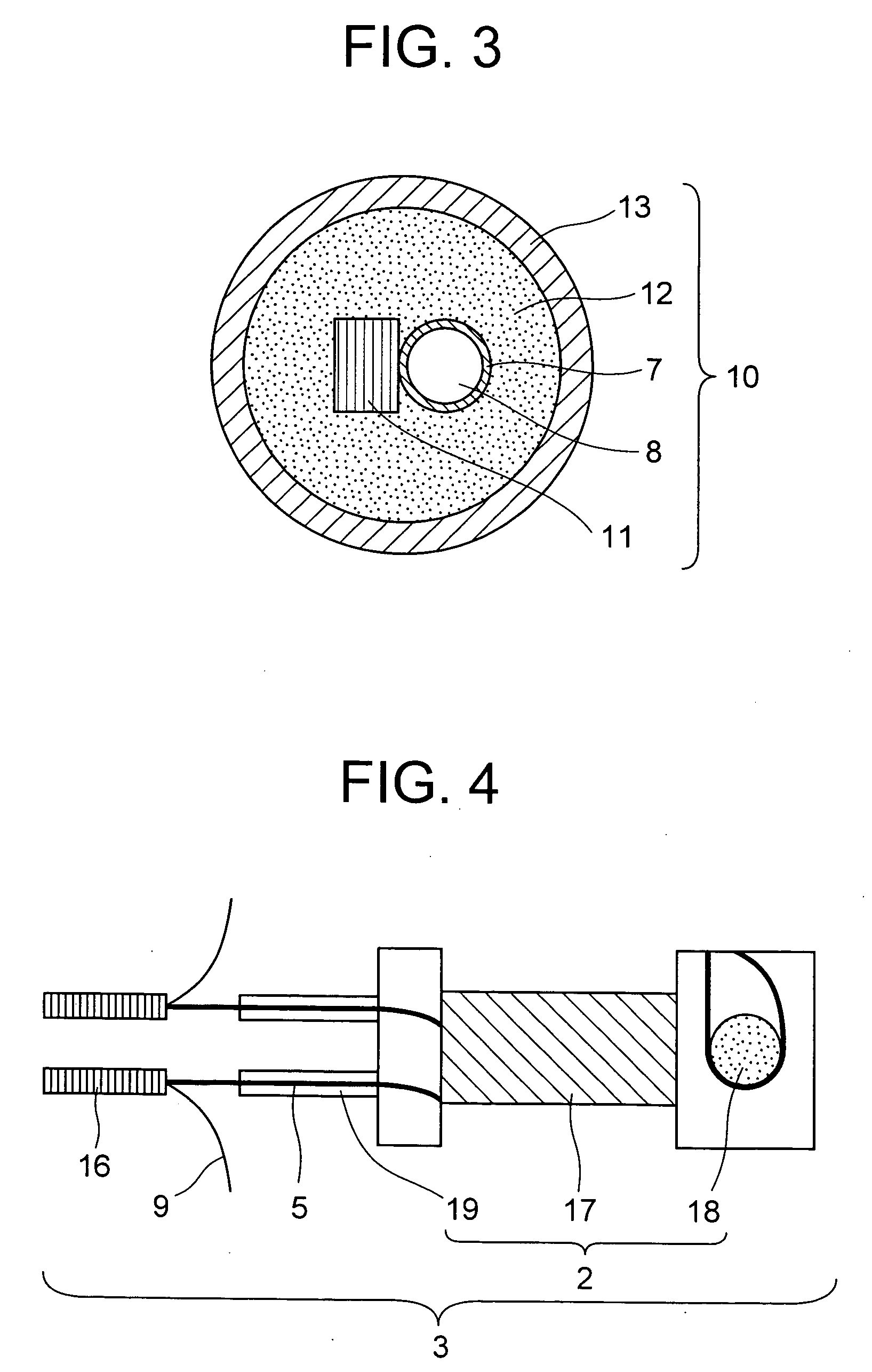
[0044]FIG. 3 shows a sectional structure of a superconductive connecting section 10 superconductively connected to this MgB2 wire 5 and a superconducting wire for a wiring line.

[0045]According to this structure, the superconducting metal 7 constituting the MgB2 wire is connected to a superconducting core portion 11 constituting the superconducting wire for the wiring line via a low-melting superconducting alloy 12 in a superconductive connection tube 13.

[0046]FIG. 4 shows a permanent current switch 3 in the present embodiment.

[0047]This permanent current switch 3 has a superconducting coil 2 and a superconduc...

example 2

[0113]An MgB2 wire 5 was prepared in the same manner as in Example 1 except that NbTi was used in a superconducting metal 7 of the MgB2 wire 5 used in Example 1 in order to improve Jc of the MgB2 wire 5. Subsequently, a permanent current switch 3 was prepared.

[0114]Moreover, the switch was superconductively connected to a superconducting wire 9 for a wiring line (an NbTi wire), and further connected to a superconducting coil 2 made of NbTi and an NbTi wire 23 for a current lead to prepare a closed circuit loop, and a permanent current test was performed.

[0115]FIG. 7 shows a relation between a time and a permanent current as an experiment result.

[0116]As a representative, a result of an energization current of 1000 A is shown. Measurement was performed for ten hours.

[0117]As a result of the measurement, it has been found that transfer to a normal conducting state did not occur even once during a permanent current operation, there was hardly a current decay and the whole closed circui...

example 3

[0124]To pass a large current through an MgB2 wire 5, the MgB2 wire was constituted to have multiple cores.

[0125]FIG. 8 shows one example of a multi-core MgB2 wire 24.

[0126]The multi-core MgB2 wire 24 has a structure in which each MgB2 portion 8 is surrounded with a superconducting metal 7, and a plurality of MgB2 portions are arranged in a high-resistance metal 6. After preparing this multi-core MgB2 wire 24, a permanent current switch 3 was prepared. It is to be noted that the MgB2 portion 8 coated with the superconducting metal 7 will be referred to as an MgB2 core.

[0127]Moreover, this structure was super-conductively connected to a superconducting wire 9 for a wiring line (an NbTi wire), and further superconductively connected to a superconducting coil 2 made of NbTi and an NbTi wire 23 for a current lead to prepare a closed circuit loop, and a permanent current test was performed.

[0128]It is to be noted that even in the multi-core MgB2 wire 24, superconductive connection is per...


PUM

PropertyMeasurementUnit
critical temperatureaaaaaaaaaa

Abstract

There is disclosed a permanent current switch which has a high temperature margin and which is thermally stable and which securely performs a switching operation between a superconducting state and a normal conducting state. The permanent current switch of the present invention has a coiled superconducting wire and a heater wire which switches the superconducting wire between the superconducting state and the normal conducting state, the superconducting wire is a magnesium diboride superconducting wire having a high-resistance metal on an outer side and a magnesium diboride superconducting portion on an inner side and prepared by forming a superconducting metal on a layer between the high-resistance metal and the magnesium diboride superconducting portion, and the permanent current switch further comprises a superconductive connecting section superconductively connected to a lead wire guided from the superconducting wire and a superconducting wire for a wiring line.

Description

BACKGROUND OF THE INVENTION[0001](1) Field of the Invention[0002]The present invention relates to a permanent current switch having a coiled superconducting wire and a heater wire, which is prepared using, in the superconducting wire, a magnesium diboride superconducting (hereinafter abbreviated as MgB2) wire (hereinafter referred to as the MgB2 wire) that exhibits a superconducting property in an environment not in excess of a critical temperature.[0003](2) Description of Related Art[0004]The MgB2 wire has a critical temperature of 39 K, which is about 20 K or more higher than that of an ordinary metal-based superconducting material. The wire also has a high critical magnetic field, and this is said to be about 50 T on a thin film. In addition, since the wire has a remarkably small anisotropic magnetic field and an excellent flexural property, it has a very few differences from the ordinary metal-based superconducting material in preparing and handling of a wire material.[0005]A pe...

Claims


Application Information

Patent Timeline
Patent Type & Authority Applications(United States)
IPC IPC(8): H01F6/00
CPCH01L39/20H10N60/355
Inventor TAKAHASHI, MASAYATANAKA, KAZUHIDEOKADA, MICHIYA
Owner HITACHI LTD
Why Eureka
Try Eureka