Focused alarm rationalization method

a rationalization method and alarm technology, applied in the direction of burglar alarms, burglar alarm mechanical actuation, instruments, etc., can solve the problems of generating more alarm events than can be effectively handled by the operator, alarm displays are expensive to design, install and maintain, and can be quite complex and flexible in their configuration. , to achieve the effect of reducing labor intensity, reducing cost and productivity, and high quality

Inactive Publication Date: 2007-08-23
PAS
View PDF2 Cites 6 Cited by
  • Summary
  • Abstract
  • Description
  • Claims
  • Application Information

AI Technical Summary

Benefits of technology

[0018] The Focused Alarm Rationalization methodology described herein provides a high quality rationalization that is a significant cost and productivity improvement over the conventional method. Various embodiments of this Focused Alarm Rationalization methodology provide one or more of (a) alarm rationalization with significantly less effort than prior art methods and therefore reduce cost, and (b) no sacrifice in performance improvement of the post-rationalized alarm system compared to the conventional methodology.

Problems solved by technology

The tags in a DCS can range from very simple, to quite complex and flexible in their configuration.
These alarm displays were expensive to design, install, and maintain, so the decision to “create an alarm” was made with care and deliberation.
The result was that most DCS systems have been implemented with very large numbers of configured alarms, and in times of process upset or even under normal circumstances, generate more alarm events than can be effectively handled by the operator.
The problem of overloaded alarm systems is well-known and has been cited in investigation reports of major process accidents.
This method is thorough, but very costly.
Since a typical DCS may involve thousands of tags, the effort can be very time-consuming and costly.
Since the people performing the review must be knowledgeable of the process under discussion, this effort takes away from their current job duties, incorporating a significant work disruption as well.
This high cost and the tedious nature of the work are large disincentives for this important safety review.
It is believed that the majority of the time spent in a conventional alarm rationalization discussion is inefficient, discussing tags that have not produced an alarm or otherwise contributed to the alarm problem of the system.

Method used


Image

  • Focused alarm rationalization method
  • Focused alarm rationalization method
  • Focused alarm rationalization method

Examples


Embodiment Construction

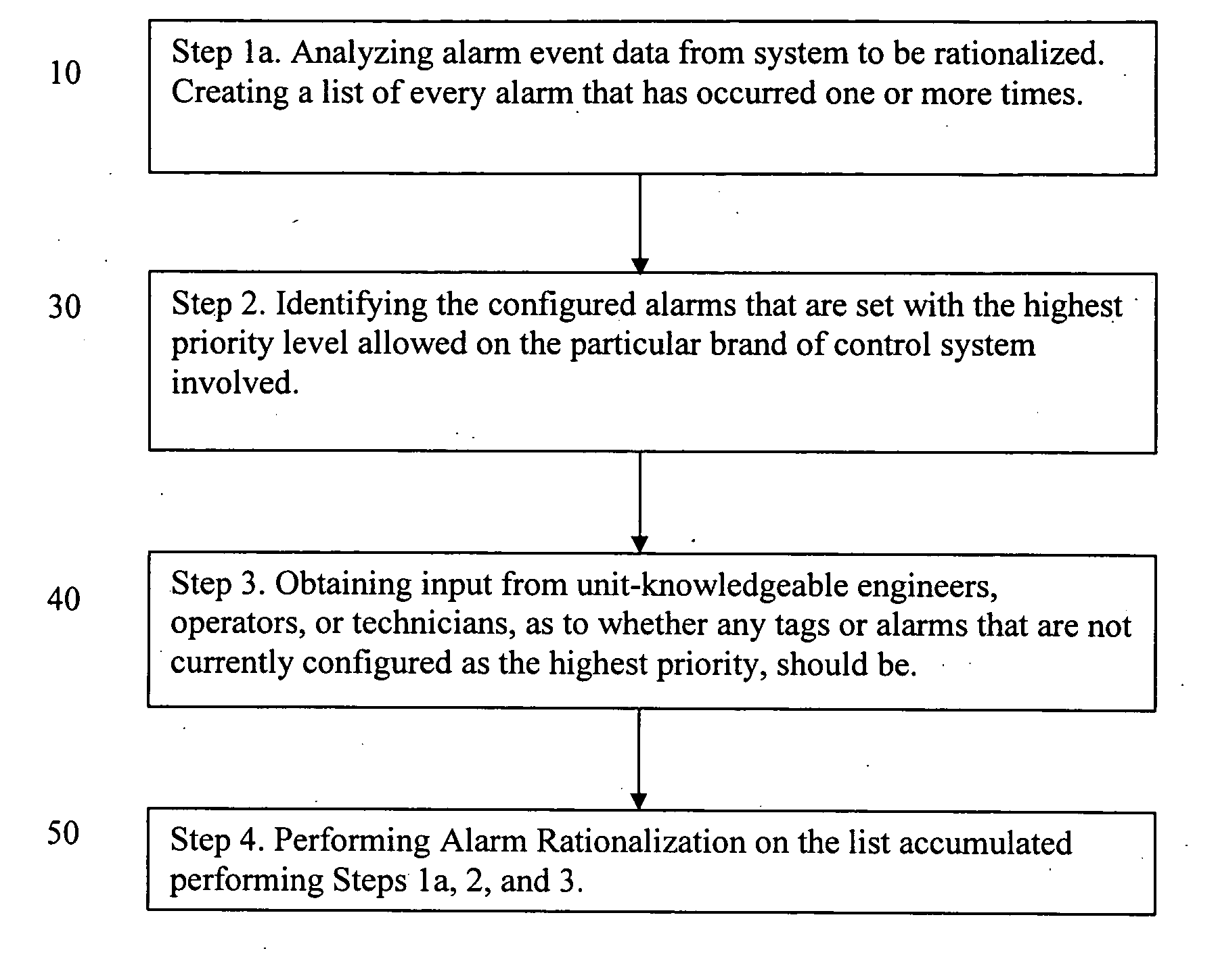
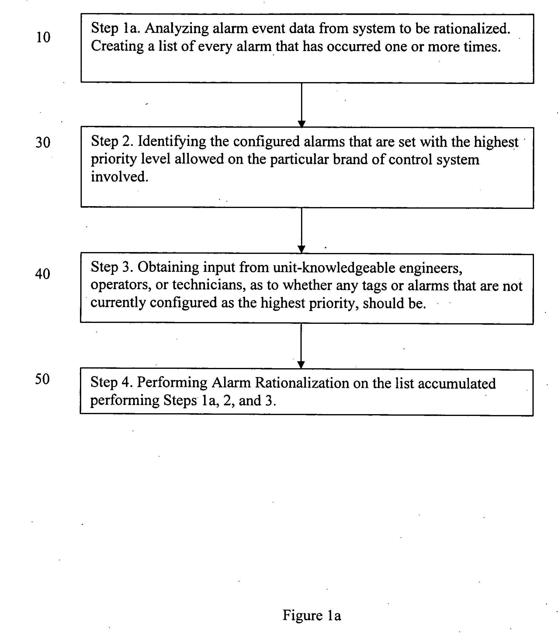
[0025] In one preferred embodiment, the invention is directed to a Three Step Focused Alarm Rationalization Methodology. The first step, Step 1a, is analyzing actual alarm event data from the system to be rationalized, as shown in block 10 of FIG. 1a. In a preferred embodiment, this analyzing is performed on data covering a time range of several months to a year or more. At least 6 months of data is a reasonable preferred minimum. Using a year's data has the advantage that any seasonal effects that influence the production of alarm events will be included. In a preferred embodiment, the analysis consists of counting and ranking all alarm events, separated by tag and alarm, from the most frequent to the least frequent during the time period. In a preferred embodiment, the results should be arranged to look similar to this:

TagAlarm TypeCount of Alarm Events ProducedFC100HIGH Value14,312FC184LOW Value12,754TI1296Bad Value10,344PSH94OFF-NORMAL10,108

[0026] The above pattern is repeated...


PUM


Abstract

This invention is directed to a method for determining an alarm configuration in industrial alarm systems. In particular, the invention relates to a method of improving an existing alarm system through a process known as “Alarm Rationalization.” The conventional method of alarm rationalization is expensive and time-consuming. The present invention is directed to a novel Focused Alarm Rationalization method that is significantly less expensive and time-consuming than prior art Alarm Rationalization methods, but which yields equivalent performance results.

Description

CROSS REFERENCE TO RELATED APPLICATION [0001] This application claims priority from provisional application Ser. No. 60 / 775,116, filed Feb. 21, 2006.BACKGROUND OF INVENTION [0002] 1. Field Of The Invention [0003] This invention is directed to a method for determining an alarm configuration in industrial alarm systems. In particular, the invention relates to a method of improving an existing alarm system through a process known as “Alarm Rationalization.” The conventional method of alarm rationalization is expensive and time-consuming. The present invention is directed to a novel Focused Alarm Rationalization method that is significantly less expensive and time-consuming than prior art Alarm Rationalization methods, but which yields equivalent performance results. [0004] 2. Description of the Prior Art [0005] A Distributed Control System (DCS) is a process control system that uses a network to interconnect sensors, controllers, operator terminals and actuators. A DCS typically contai...

Claims


Application Information

Patent Timeline
Patent Type & Authority Applications(United States)
IPC IPC(8): G08B13/14
CPCG08B29/18G08B25/00
Inventor HOLLIFIELD, BILL R.
Owner PAS
Why Eureka
Try Eureka