Image pickup apparatus
a technology of image pickup and focusing device, which is applied in the direction of focusing aids, instruments, television systems, etc., can solve the problems of increasing the body size and fabrication cost of electronic cameras, requiring additional time before focusing, and it is difficult to apply this technology to all electronic cameras. to achieve the effect of reducing the continuous shooting interval tim
- Summary
- Abstract
- Description
- Claims
- Application Information
AI Technical Summary
Benefits of technology
Problems solved by technology
Method used
Image
Examples
first exemplary embodiment
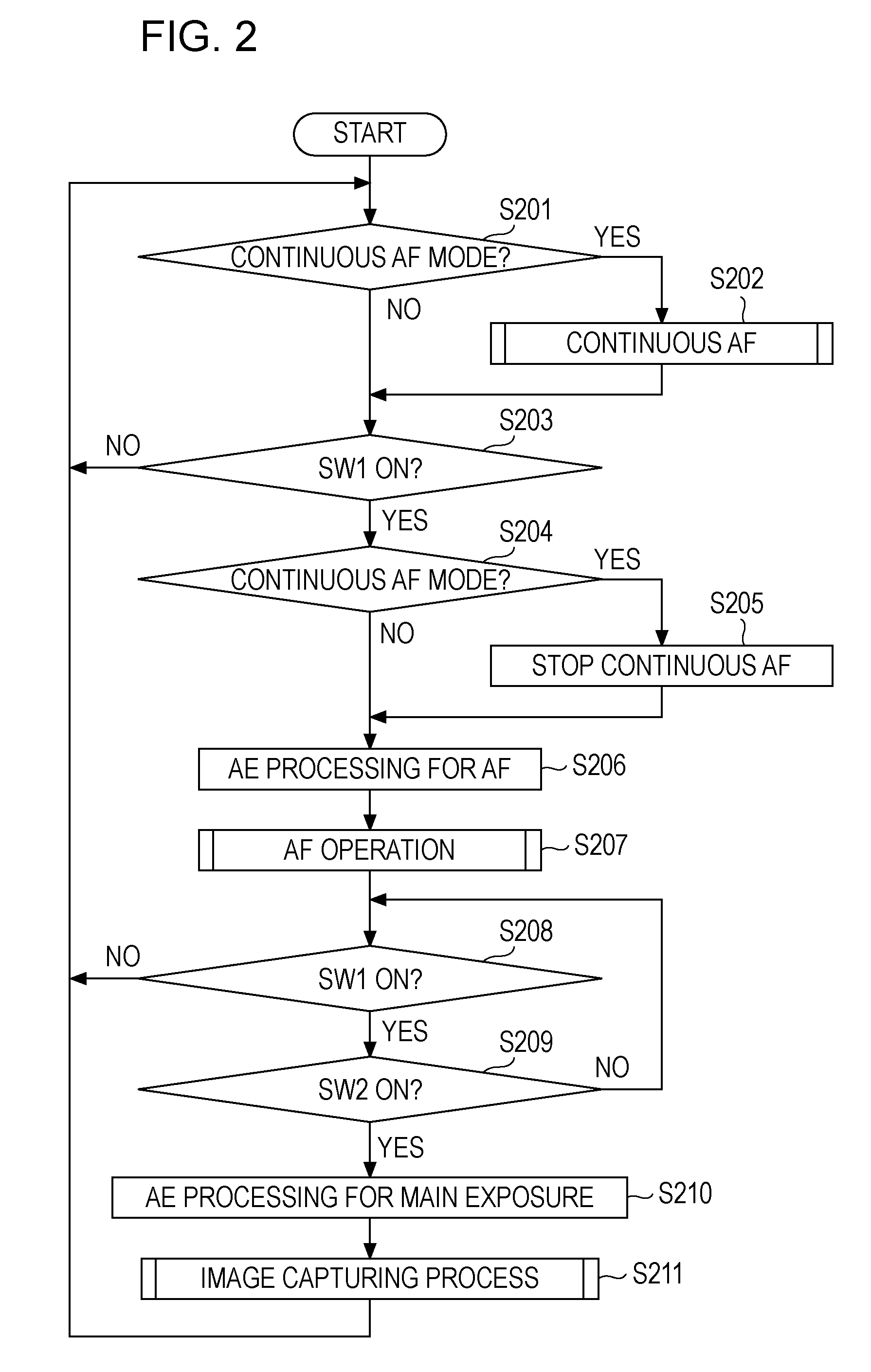
[0038]A first exemplary embodiment of the present invention is described below with reference to the accompanying drawings. In the first exemplary embodiment, the focus control operation during a continuous shooting interval is achieved even in a system that cannot compute the focus evaluation value and perform image processing on a main exposure image signal at the same time due to resource contention.
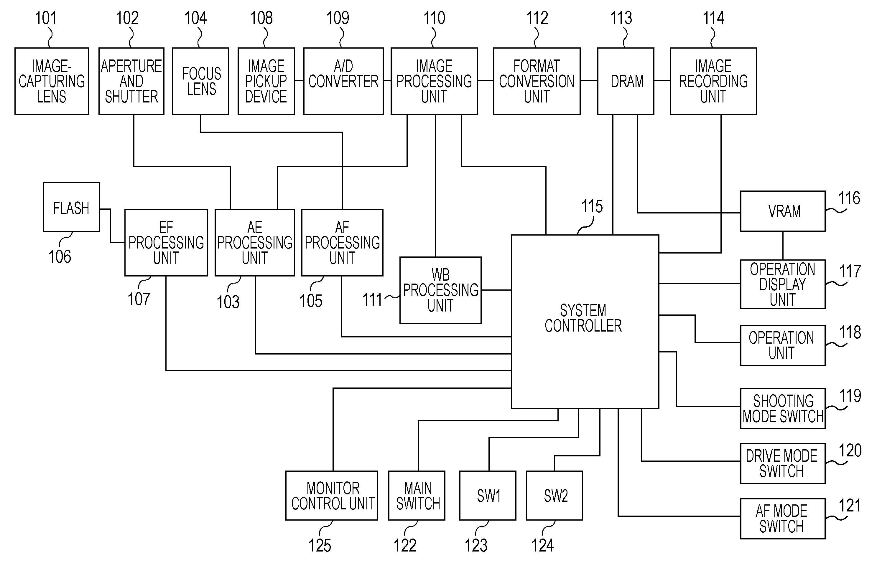
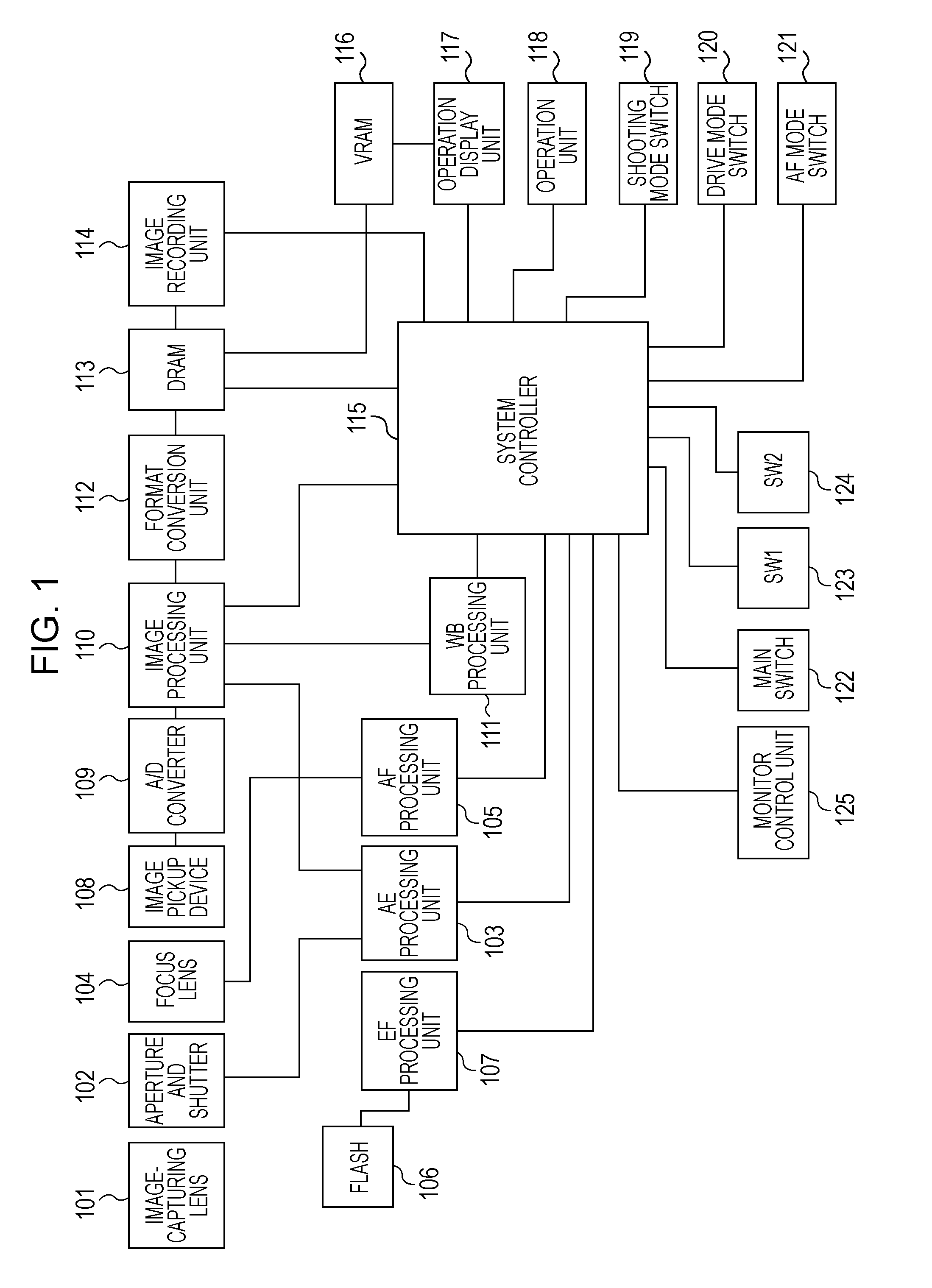
[0039]FIG. 1 is a block diagram of an exemplary circuit configuration of an electronic camera system according to the first exemplary embodiment of the present invention. The electronic camera system includes an image-capturing lens 101 having a zoom mechanism, an aperture and shutter 102 for controlling the amount of light, and an AE processing unit 103, a focus lens 104 for focusing light on an image pickup device, an AF processing unit 105, a flash 106, an EF processing unit 107, and an image pickup device 108 serving as a light detecting unit or a photoelectric conversion unit for...
second exemplary embodiment
[0107]A second exemplary embodiment of the present invention is described next with reference to the accompanying drawings. In the second exemplary embodiment, a focus control operation can be achieved in a system in which the computation of the focus evaluation value and image processing of the main exposure image signal can be performed at the same time. Additionally, in this system, the setting of the scan range of the continuous shooting AF can be performed earlier than that in the first exemplary embodiment.
[0108]According to the second exemplary embodiment, the circuit configuration of an electronic camera is similar to that shown in FIG. 1. In addition, since the basic operation of the second exemplary embodiment is similar to that of the first exemplary embodiment shown in FIGS. 2 to 4, description thereof is not repeated. However, the image capturing operation and the focus control operation in the continuous shooting interval may be different from those of the first exempl...
third exemplary embodiment
[0130]A third exemplary embodiment of the present invention is described next with reference to the accompanying drawings. According to the third exemplary embodiment, the system configuration is similar to that of the second exemplary embodiment. In addition, in this configuration, when an actuator operates, noise does not have a negative impact on the main exposure image signal. For example, an actuator for driving the focus lens 104 is disposed distant from the image pickup device 108 and the A / D converter 109.
[0131]In such a configuration, since noise caused by the operation of the actuator needs not to be taken into account when the main exposure image signal is read out, the focus lens 104 can be moved immediately after the shutter is closed, as shown in FIG. 18. Accordingly, the continuous shooting interval AF process can be efficiently performed.
[0132]According to the first to third exemplary embodiments of the present invention, the following advantages can be provided.
[013...
PUM
 Abstract
Description
Claims
Application Information
 - R&D
- Intellectual Property
- Life Sciences
- Materials
- Tech Scout
- Unparalleled Data Quality
- Higher Quality Content
- 60% Fewer Hallucinations
Browse by: Latest US Patents, China's latest patents, Technical Efficacy Thesaurus, Application Domain, Technology Topic, Popular Technical Reports.
© 2025 PatSnap. All rights reserved.Legal|Privacy policy|Modern Slavery Act Transparency Statement|Sitemap|About US| Contact US: help@patsnap.com


